18 minute read
Automation of infrastructure inspection & maintenance in Network Rail

by The PWI

AUTHOR: Gareth Evans
Gareth is a Chartered Engineer and a Fellow of the PWI.
Advertisement
Gareth’s early career was in the steel industry, manufacturing railway products and delivering technology and asset management projects for heavy and light rail clients. Joining Network Rail in 2009, Gareth has been Head of Track since 2016. He has accountability for Network Rail’s national standards and competence frameworks, and the R&D programme for track engineering. He is focussed on addressing the strategic challenges of improving safety and reliability of track infrastructure, mitigating the effects of weather and climate change and delivering decarbonisation of the railway system.
Our industry is facing unprecedented challenges with recent events triggering a top-to-bottom review of how we inspect and repair the fixed assets that make up our railway infrastructure. The tragic workforce fatalities at Margam in 2019, Roade in 2020 and Surbiton in 2021 have led to enforcement action against Network Rail and an acceleration of changes to the way our frontline teams access their assets safely for inspection and maintenance. The global COVID-19 pandemic has challenged our assumptions about passenger growth and whether the pattern of use will return to pre-pandemic levels. Given the necessary resource put into supporting the UK through COVID, our industry is also now challenged to accelerate innovation and change to deliver a more efficient railway system providing better value for money for UK taxpayers.
Automation of infrastructure inspection and maintenance, when carefully designed and implemented, offers part of the solution to the challenges we face.
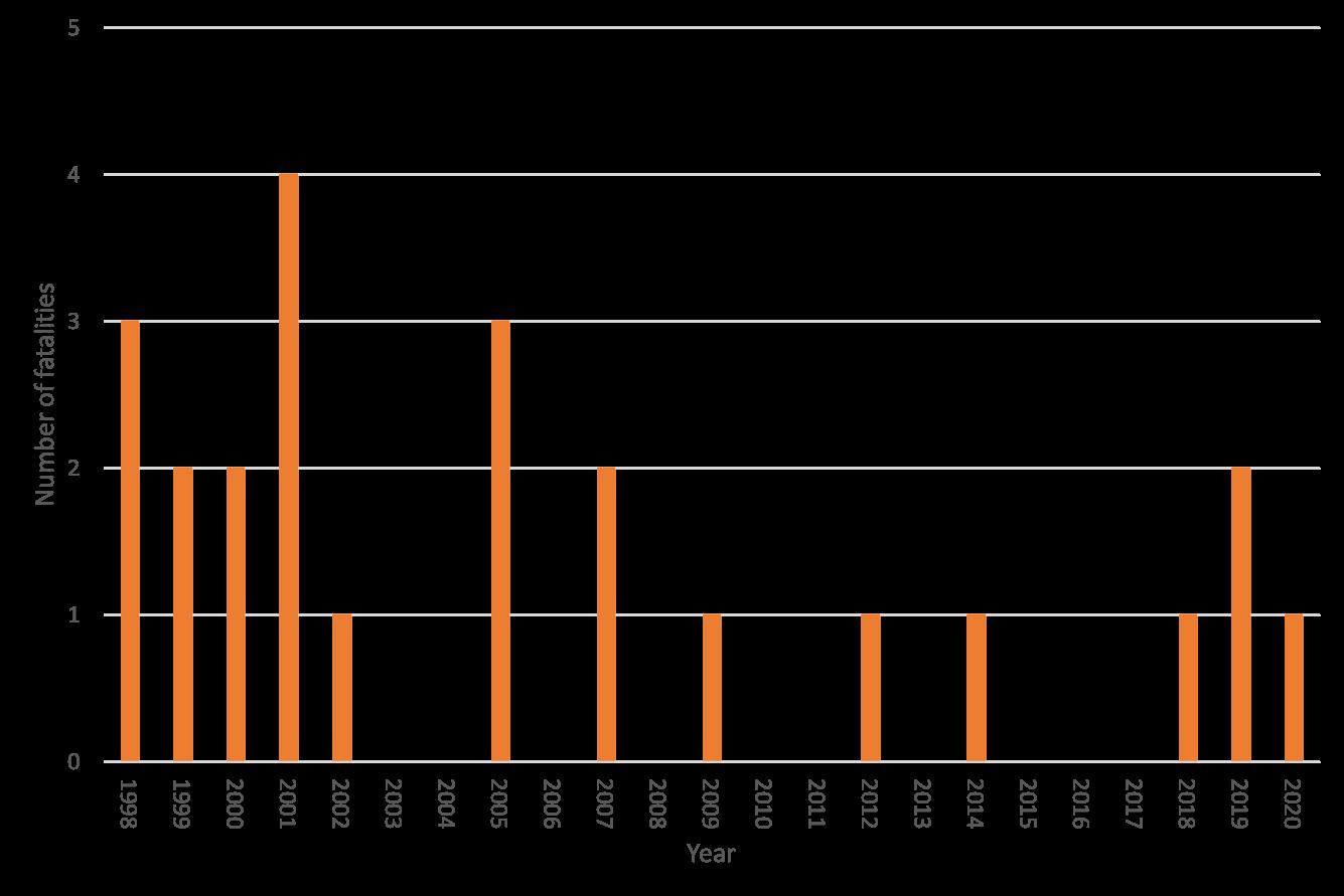
So, our first objective is to improve safety for anybody working on the railway. We need to reduce the risk of harm from traffic to trackworkers, as UK data shows we have not made great improvements in this area over the last five years (figures 1a and 1b). We also need to continue to improve the health of our frontline teams by reducing their exposure to risks associated with conventional ways of working, for example manual handling and hand-arm vibration syndrome (HAVS).
Our second objective is to improve the capacity of the railway. Automation allows us to introduce more reliable and reproduceable methods of inspection and repair, as well as increasing the productivity of maintenance of our fixed assets.
Our third objective is to reduce the cost of running the UK railway. Two examples where we’ve done more detailed analysis show the business benefits that could be achieved. By automating the process for repairing rail head defects we could save £91M over a typical five-year funding period. By automating our inspections of tunnels, we can reduce the ‘on track’ examination time by 96%.
Lastly, we need to align with the agreed technical strategy for UK railways, published in autumn 2020. One of the five key objectives of this strategy, reliable and easy to maintain infrastructure, relies on the introduction of greater levels of automation and mechanisation of fixed asset inspection and maintenance to deliver the 2040 vision agreed by wider industry. SO HOW IS NETWORK RAIL RESPONDING TO THIS CHALLENGE?
Working closely with academia and our supply chain partners (eg via UKRRIN, other UK funded research and EU Horizon 2020 programmes) we have created a cross-asset Autonomous Intelligent Systems (AIS) research and development strategy, comprising of three themes:
1. Smart data collection – using state-of-the-art sensor technology, either fixed to the infrastructure or mounted on mobile platforms such as service trains, to collect more and better quality data about our asset, providing that data more quickly to the engineers who need it to make decisions about where and when to intervene. 2. Autonomous planning – to support this we are developing tools and techniques to help plan maintenance intervention based on our enhanced knowledge of asset condition and the rate of change of condition. 3. Autonomous robotics – to deliver workforce safety and maintenance productivity benefits.
Our vision (figure 2) is to construct scalable architecture that allows us to grow the scope of autonomous intelligent systems, using a wide range of asset data and information sources about the condition of the asset, using commercial off the shelf technology to future proof the system architecture, and to provide us all with the functionality we need to evolve and grow this capability in future years. At the heart of our AIS will be the corporate ‘brain’, the database of all asset information aligned to a single common geospatial referencing system for the location of assets and faults, taking in data collected by frontline teams, rolling stock and unmanned drones/robotic inspection platforms. We will then use our advanced analytics capability to investigate patterns and trends in asset behaviour. Initially this new knowledge will be presented to our engineers and their teams to support decisions about where, when and how to intervene to address faults. Longer term, the vision is for certain forms of maintenance to be scheduled automatically based on the outputs from asset condition data analysis.
So now to some examples of new technology that is being developed to move us towards this future vision. The first of these is development of our Plain Line Pattern Recognition (PLPR) capability. We already run a fleet of trains over 75% of our plain line track that use high-definition video and automated image analysis algorithms to inspect for a small number of failure modes.
Figure 1a: Number of fatalities as a result of trackworkers being struck by trains for each year between 1997 and 2020 (source: RAIB).
Figure 1b: Number of near misses involving trackworkers 2015/16 – 2019/20 (source: RSSB Annual Health & Safety Report 2019/20).

We are enhancing the scope of the algorithms to start automatically detecting a larger range of faults and component types. For example, the introduction of a new algorithm to detect clamped rail joints and present images of missing/loose clamps and/or fishplates to NR inspectors to verify and categorise the severity of the defects. The recent acceleration of our track worker safety programme has prompted another review of how existing PLPR imagery can be used to deliver inspections differently without compromising system risk. For example, figure 3 shows PLPR an image of rail foot corrosion, which when combined with rail depth data collected by our Ultrasonic Test Units (UTUs), could replace our themed manual inspections of rail in tunnels.
Figure 4 shows another PLPR image of a rail running band, in this case the running band exhibits localised widening that could indicate the presence of a vertical longitudinal split defect. By automating measurement of the change in width and location of the running band, and combining this with other rail inspection data we may be able to automate another set of themed manual inspections of rail condition. We are also developing the facility to capture and store the PLPR video images of every S&C unit our PLPR trains travel over, in order to potentially reduce the amount of ‘boots on ballast’ time inspecting our newer, more robust S&C assets. Another example of improvements to our mobile monitoring capability is in rail flaw detection. Our UTUs inspect running rails for cracks and wear at speeds of up to 35mph, using ultrasonic, eddy current and laser profiling technology. However, the current inspection speed limitations pose challenges when planning the UTUs into the timetable. Through our R&D programmes we are now investigating whether there are new emerging technologies that can do the same job but at higher speed. Longer term this will allow us to introduce a trainborne rail inspection process that is easier to plan, more reliable and less disruptive to our passenger and freight customers.
The final example of improvements to our mobile monitoring technology is research we are doing to measure, from a train, the rate of change of track stiffness on our network. This would allow us to identify locations where we have underlying design and construction issues that lead to repeat rail and geometry faults, so we can start to address the root causes of these faults. We have fitted sensors to our NMT infrastructure monitoring train, to both the power car and measurement car. Since each vehicle has different axle loads, it is possible to measure the difference in vehicle response to the same track geometry and from this calculate the dynamic stiffness of the track system.
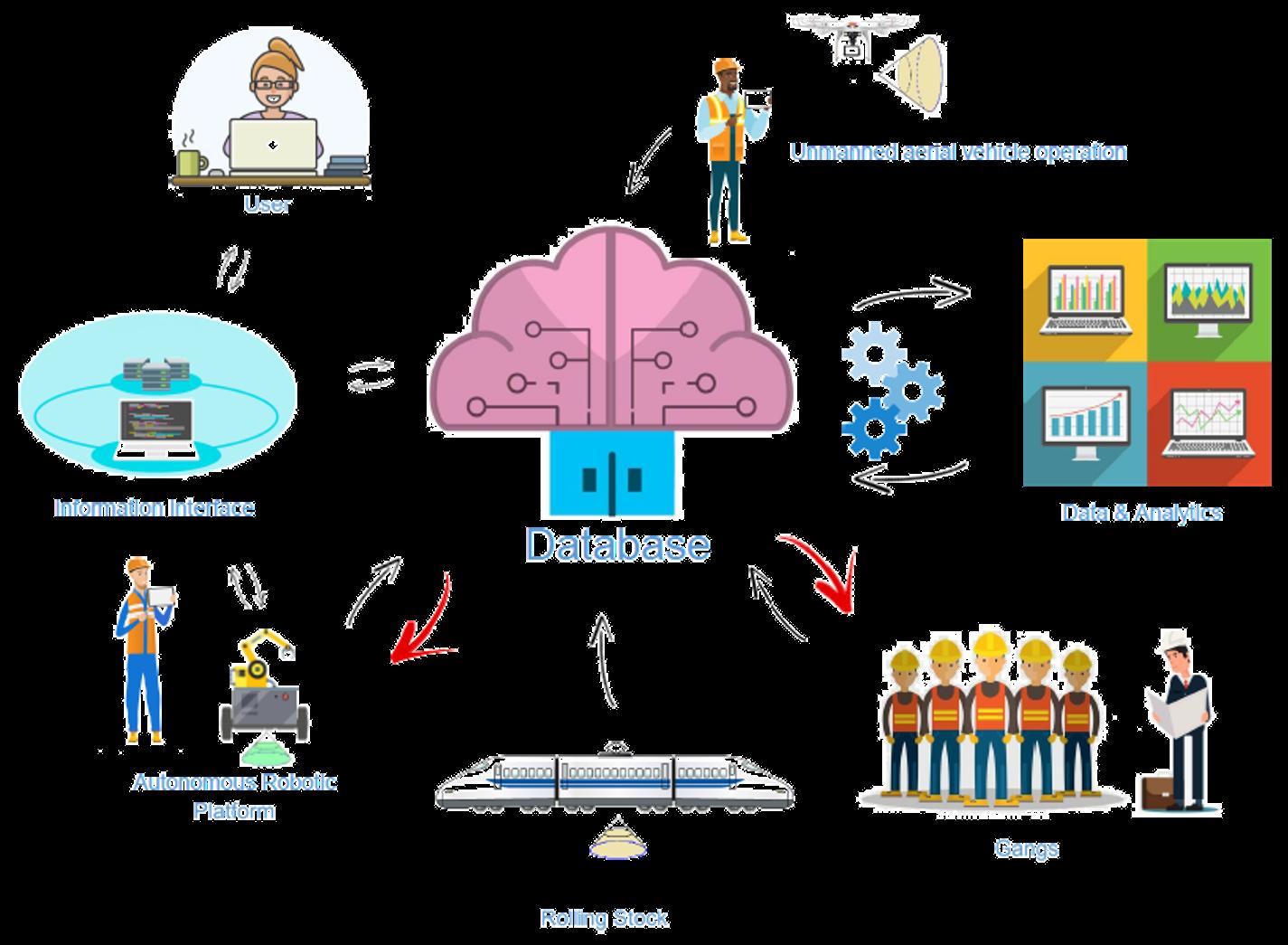
Figure 2. Network Rail’s vision for autonomous intelligent systems connecting inspection and data analysis to end users and frontline engineering and maintenance teams.
Of course, with all the new exciting data streams from mobile monitoring, it is vital we can integrate the data in order to convert it to knowledge and understanding about the condition of our assets. Our Intelligent Infrastructure programme is building a decision support tool for track engineering that does just that. We have already aligned all of our track geometry data and traces (figure 5) and have developed algorithms for calculating and then predicting the rate of change of track geometry deterioration. We’ve introduced a cyclic top dashboard (figure 6) providing users with visualisation of existing cyclic top faults as well as geometry features that could develop into future cyclic top defects. As reported by authors in this edition of the PWI Journal, we are also investigating how to exploit the track geometry data we already collect to monitor the condition of earthworks, specifically embankment stability. Combined with use of satellite monitoring technology this has the potential to significantly enhance our understanding of the behaviour of these assets, again allowing us to target investment and treatments at the highest risk locations.
Over the next two years we will increase the functionality of this tool to include all of our rail condition data (ultrasonic defects, eddy current RCF measurements, rail side wear and head wear measurements). The addition of track geometry and


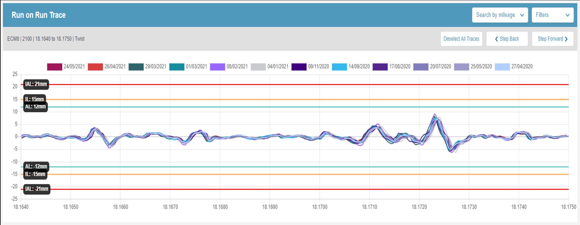
Figure 5: Example of track geometry trace-on-trace alignment capability in the Network Rail Insight decision support tool. This shows alignment of 35m top measurements for a single rail collected over a twelve month period.
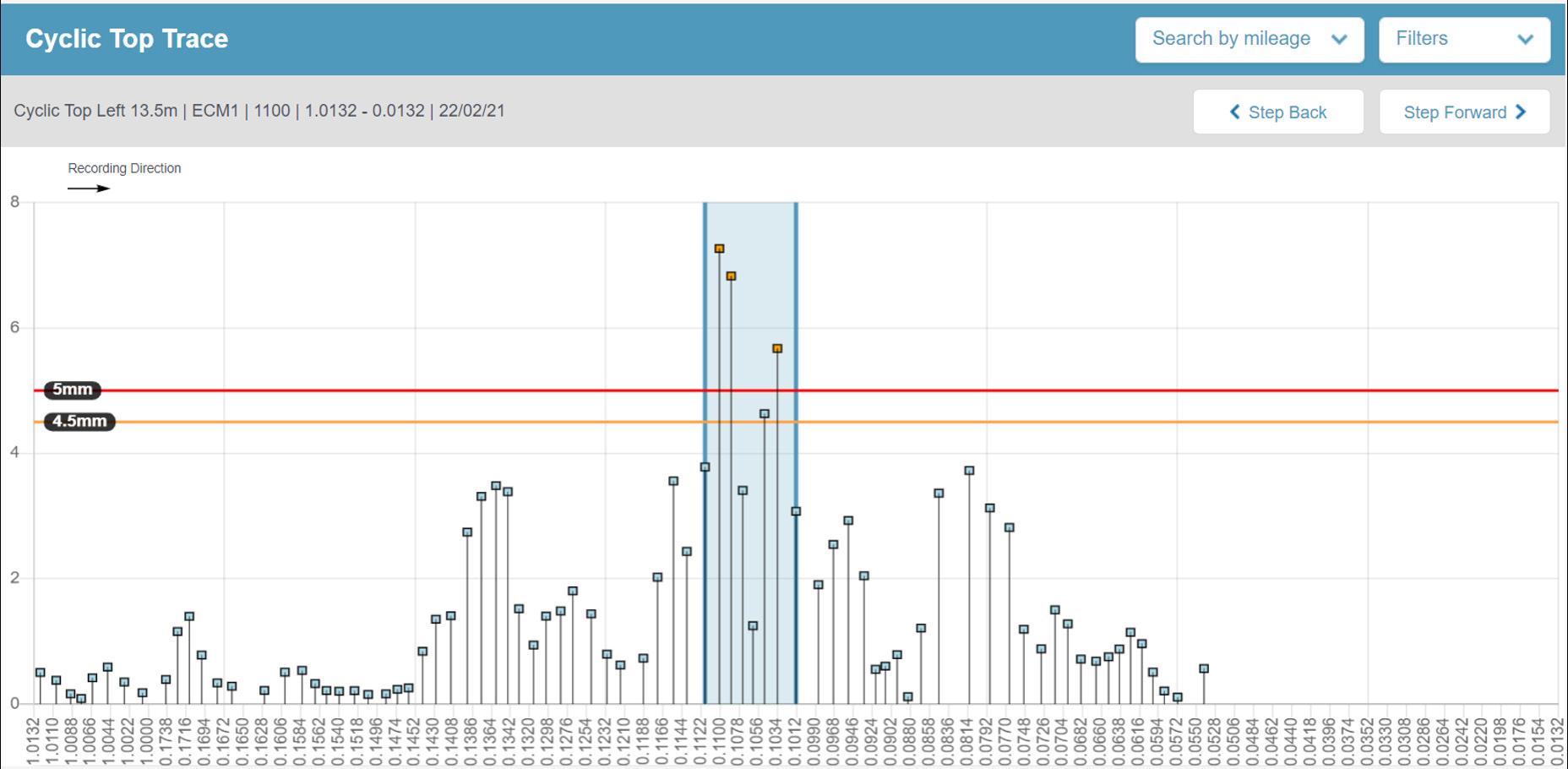
Figure 6: Example of cyclic top data visualisation in the Network Rail Insight decision support tool. This shows data for a single rail in the 13.5m wavelength band, highlighting vertical deviations that exceed the threshold (denoted by the red horizontal line) for cyclic top and which trigger Network Rail geometry data analysis algorithms to start summing up the effect of a sequence of these features. The level of corrective maintenance action required depends on the number and severity of sequential features that exceed the threshold value.
track quality data from inspection systems mounted on service trains, structure gauging data, and S&C inspection data will create a tool that provides our track engineers with a metre-by-metre insight into the health of their asset, and the condition of other assets such as drainage and earthworks, for a full system view of the root causes of track degradation.
Moving on to fixed sensors, we are researching the potential of our fixed fibre optic cable infrastructure to monitor the health of track, converting it to 20,000km of continuous, network-wide, remote condition monitoring. The focus initially is to demonstrate if this technology can be used to monitor train position, vehicle type, speed and direction of travel.
As we gain more confidence in the data, we intend to apply the technology to understanding the rate of deterioration of the track. A high priority use case is whether we can detect wrong side failure events such as broken rails and track buckles, to reduce the risk of trains travelling over these hazards. We’re also interested in whether we can monitor wheelset condition and deterioration, for example how quickly wheel flats develop. If so, then we will be able to update the way we respond as an industry to changes in wheelset condition, introducing a greater degree of predictive analysis and less disruptive corrective actions.
Now for the third strand in our AIS strategy; the autonomous inspection/maintenance vehicle itself. We have determined through extensive stakeholder consultation that we require a more agile approach to inspection and maintenance, for example other delivery platforms to complement our existing trainborne inspection fleet. We are building the system architecture to allow us to ‘plug and play’ a number of options for the automated inspection and maintenance vehicle.
We have research looking at the command-and-control systems that will be required, including navigation to and from worksites. We are looking at the options for the vehicle chassis itself, so it provides the right level of flexibility in terms of the tasks that can be delivered.
• Automated rail head inspection and repair • Wet bed treatment and drainage installation • Stretcher bar installation • Automated tunnel inspection • Drones to inspect enclosed spaces, for example mine workings • Overhead line equipment inspection
But when we talk about autonomy, how much autonomous operation are we looking to build into our technological developments?
Network Rail is basing its requirement specifications on the NASA FLOAAT (Function-specific Level of Autonomy and Automation Tool) scale (figure 7). Network Rail’s research is focussing on projects with Level 2 or 3 autonomy, with the operator very much in the loop for carrying out the task. In the future we’re aiming to migrate to Levels 4 and 5, with systems carrying out initial elements of analysis and ranking, for confirmation by the operator.
We have developed a web-based operator interface used to control an autonomous vehicle system, in a simulated environment (figure 8). The operator selects tasks from a pre-existing job list, reviewing the details of the work before confirming this is the correct job. The location of the autonomous vehicle and the location of the worksite are displayed, and the operator requests the vehicle to move to the worksite, monitoring its progress. The vehicle is capable of obstacle detection, with operator verification of whether certain features can be passed safely. The vehicle automatically regulates its own speed on the approach to the worksite. On reaching the worksite the operator selects from a predefined set of robot arm operations to complete each stage of the inspection and/or repair task.
To build this concept in a live railway environment Network Rail has purchased a Warthog all-terrain remotely operated vehicle (ROV) as the platform for specific use cases (figure 9). The first use case being developed is automated ultrasonic rail inspection, coupling existing ultrasonic inspection trolleys with the Warthog ROV. The prototype autonomous vehicle will receive a ‘Start’ instruction and will then inspect a length of track, analyse the inspection data using artificial intelligence to classify the type and severity of rail defects, and then return down the same track accurately marking defects that have been identified. When all defects are marked the vehicle will return to its start position. • Conversion of the autonomous road vehicle to run on railway track • Addition of ultrasonic inspection capability (proven technology) • Develop communications between ultrasonic inspection trolley systems and the autonomous vehicle • Develop artificial intelligence (AI) for analysis of ultrasonic inspection data – (using Sperry system Elmer®) • Develop communication between AI and the autonomous vehicle • Develop enhanced positional information and control systems to ensure defects are accurately identified.
We are aiming to demonstrate the prototype arrangement during 2021. However, the future concept is actually fully automated inspection and weld repair of the rail running surface and restoration of damaged crossings in S&C, including laser scanning of damaged areas to correctly size and define the level of weld repair required, and automated re-profiling of the weld-repaired rail/crossing surface.
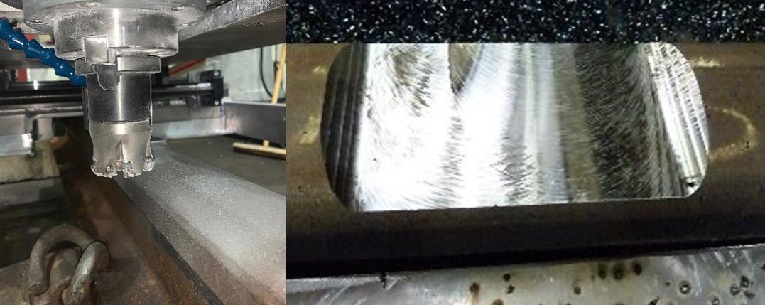
Our objective is to develop the system to Technology Readiness Level 7 by December 2022, operating a full-scale technology demonstrator in the railway environment. The Discrete Defect Repair technology (figure 10), developed in partnership with ARR RailSolutions Ltd, is currently a working prototype which includes CNC milling for rail defect excavation, preheating of the area to be welded, CNC flux-cored arc welding, automated weld surface cleaning and final CNC weld re-profiling and measurement, restoring the original profile of the rail head or crossing. The process delivers a high integrity rail surface repair which has been fully tested by laboratory fatigue testing.
For one final example of automation in track inspection, we are developing equipment to automate the TRK053 detailed examination of switches, used to identify potential derailment hazards at the wheel-rail interface. Italian company Loccioni originally developed their ‘Felix’ technology for RFI, the company managing the Italian Railway Infrastructure (figure 11). Over the last two years we have worked with Loccioni to make sure the system has the full range of reference data for Network Rail assets, building the capability to inspect our most common S&C types including full depth vertical, NR56V, RT60, NR60 Mk1 and NR60 Mk2 designs.


Figure 8: Example of prototype operator interface (top) for control of an autonomous vehicle system in a simulated environment (bottom).

Current methods of checking for switch derailment hazards are based on manual checks using a standard set of track gauges – the process has an inbuilt level of repeatability and reproducibility. Moving to the Felix system will introduce a greater level of consistency and accuracy into switch derailment hazard inspections. It also speeds up the process, with full recording of a single turnout taking approximately 10 minutes (depending on turnout length).
Felix records laser rail profiles of all parts of the S&C as well as static gauge and cross level, matching measured profiles to wheel and rail profiles.
We have been working with Loccioni to modify the system hardware and software in order to be able to measure the following parameters required by Network Rail switch inspection standards:
• Switch rail seating gap • Squareness of switch toes • Residual switch opening • P8 profile measurement • Gauge 1 & 2 assessment • Back-to-back gauge measurement
While COVID has delayed some of the site-based activity required to program Felix for use on Network Rail infrastructure, we are hoping to begin full operational trials with our maintenance delivery units from autumn 2021.
So, there is a lot of very exciting work going on, new ideas and technology that Network Rail is looking to bring to the railway infrastructure. BUT there are a number of challenges we must address if we are going to successfully introduce the technological change.
Our first challenge is to bring our workforce with us on this journey introducing automation is a significant step change. We’re going to have to make sure our people have access to the skills, knowledge, and expertise they are going to need to work with the new technology with confidence. We should not underestimate the scale of this task, but we need to make a start.
Our next challenge is how we manage the data that these systems produce. As we fit more and more sensors and increase the scope and scale of mobile monitoring, we will generate an order of magnitude more data. We have to create a system architecture that allows us to store, process and share this data.
More importantly, we have to build the algorithms and tools that convert the raw data into more valuable information and knowledge to support our frontline teams as they make safety-critical decisions about where, when and how to intervene to prevent or correct asset faults. We also have to make sure that the systems which store, record and analyse all of this data are secure, have the appropriate controls and governance associated with managing the data and systems, and are future-proofed so they are scalable and can be enhanced without requiring costly ‘big bang’ IT upgrade projects.
A further challenge that affects us all is climate change. Not only will our assets need to be more resilient to the predicted changes in weather patterns as our climate warms but all of the systems we use to remotely monitor asset behaviour and condition also need to be And finally, all of these developments and challenges need to be wrapped up in the safety case for the wider business change. This is where we can apply the Common Safety Method Risk Assessment to make sure we have reviewed all of the hazards, have designed, agreed and implemented suitable mitigations, and all of the governance and regulation that needs to surround the use of more autonomous asset inspection and repair vehicles is carefully considered and constructed as part of the wider programme.
Figures 10 A - D: The three stages in the fully automated Discrete Defect Repair process for weld repair of rail and crossing surface defects. All images courtesy of ARR RailSolutions Ltd.

A: Pre-repair laser rail head profile measurement. Examples of measured profiles (overall and gauge corner detail) are shown on the right.

C: Automatic computer-controlled flux cored low pre-heat arc welding (left) with inter-layer peening (right).
D: Final CNC machining to profile and automated weld profile quality check.