13 minute read
Earthing and bonding on a.c. electrified railways: Benefits of protection reliability and an alternative approach to ‘if in doubt, bond-it-out’

by The PWI

Benefits of protection reliability and an alternative approach to ‘if in doubt, bond-it-out’
Advertisement
AUTHOR: Dr Paul Naylor BEng(Hons) PhD CEng MIET
Dr Paul Naylor has over 21 years’ experience of railway electrification and five years in extra-high voltage cable systems. He holds a degree in electrical and electronic engineering and a PhD in the transient response of high-voltage (zinc-oxide) surge arresters. Paul has led a team responsible for modelling a.c. and d.c. electric traction systems.
He has developed the NR standards for autotransformers and high-voltage cabling and wrote the testing requirements for the autotransformer conversion on the WCML. Paul is currently a Principal Engineer and has led the drafting of the system design principles standard for a.c. electric traction (NR/L2/ELP/27275) and for earthing and bonding on a.c. electrified railways (NR/L2/ELP/21085).
Railway electrification delivery and costs have been greatly affected by the challenges in providing earthing and bonding. This has, in a number of cases, led to a substantial amount being spent on bonding.
This article provides an overview of protective measures by way of earthing and bonding requirements for ac electrified railways, detailing the role of a reliable protection system and an approach that has been written into a revised Network Rail Standard and which is being adopted on new electrification schemes. Use of this revised approach reduces the amount of equipment that needs to be bonded, resulting in a reduction in both installation and maintenance costs. EARTHING AND BONDING
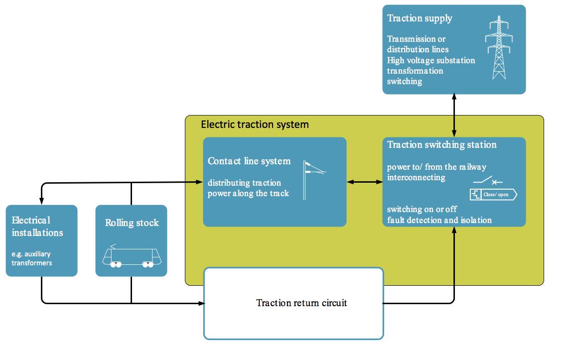
In its basic form, the ac electric traction system comprises an overhead contact line system and a traction return circuit. The overhead contact line system transmits electric energy from the source substation to the trains and other electrical installations connected to the contact line system. The traction return circuit collects and conducts the return current from the trains (and other consumers) and returns it back to the source substation.
The electric traction system and the functional interfaces with the traction return circuit are shown in figure 1.
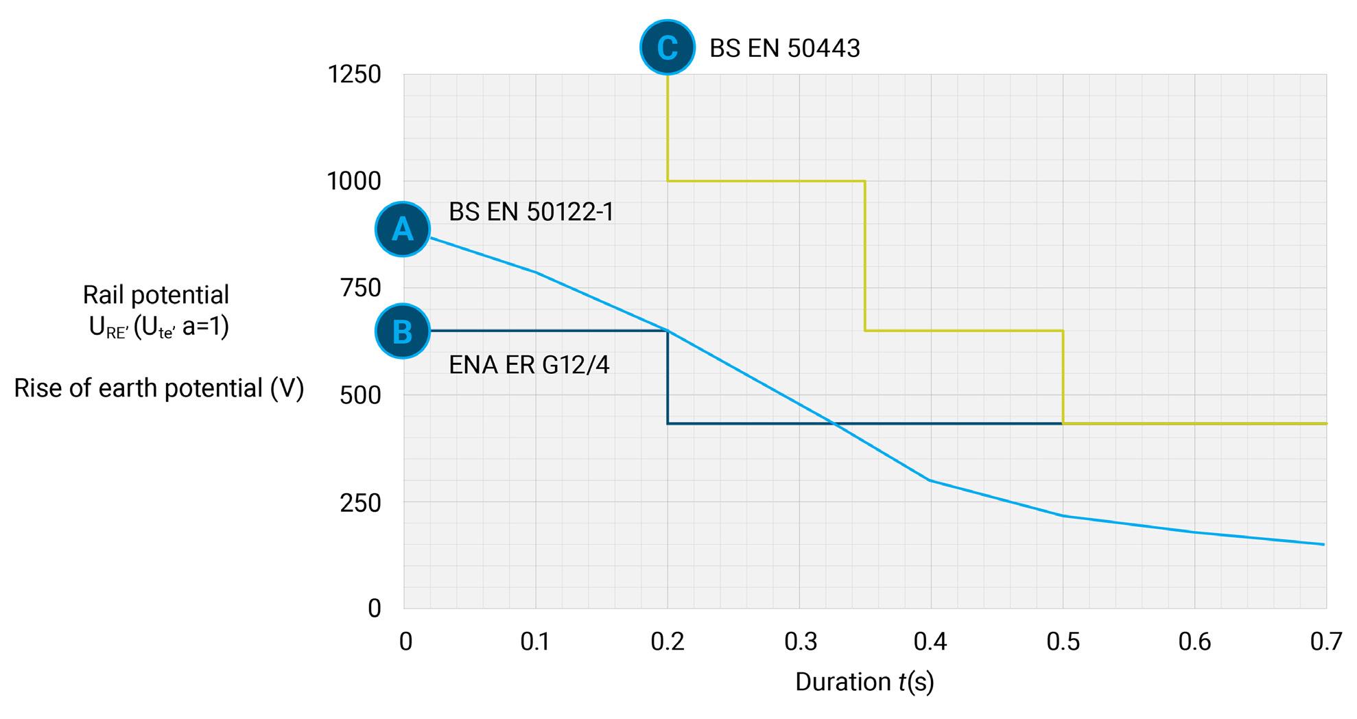
Figure 2: Short-term rail potential / earth potential rise limits.
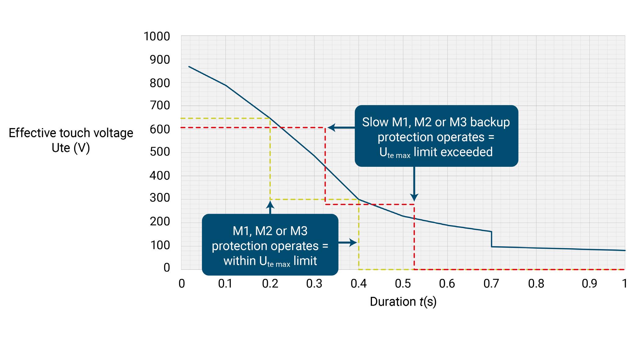
Figure 3: Protection system – effective touch voltages and fault clearance duration.
The traction return circuit consists of all conductors that form the intended path for the traction return current. The principal conductor(s) that form the traction return circuit are the traction return running rails and also comprise return conductors/cables and return conductors for booster transformer systems – each of which are electrically connected to the traction return rails. In its simplest form the traction return circuit can be considered as being the neutral conductor in a single-phase circuit.
The return circuit is also intrinsically connected to earth – the connection to earth is mainly formed by two main connections, these being via the foundations of the overhead line structures or via the rails themselves.
The traction return circuit therefore acts as the protective conductor in the electric traction system and provides a low-impedance path for fault current, for example a short-circuit caused by a broken contact line touching the traction return circuit or parts connected to the traction return circuit (such as the overhead line structures). The earthing and bonding system within the overall electric traction system is designed to:
• provide a low impedance path for operational traction return current • provide a low impedance path for operational traction return current and short-circuit fault current and thus allow faults to be detected and cleared quickly • keep the potential of the traction return circuit and equipment connected to the traction return circuit close to earth potential
The earthing and bonding system is designed to reduce the touch voltages for long-term (operational) and short-term (short-circuit fault) conditions to be within safe limits.
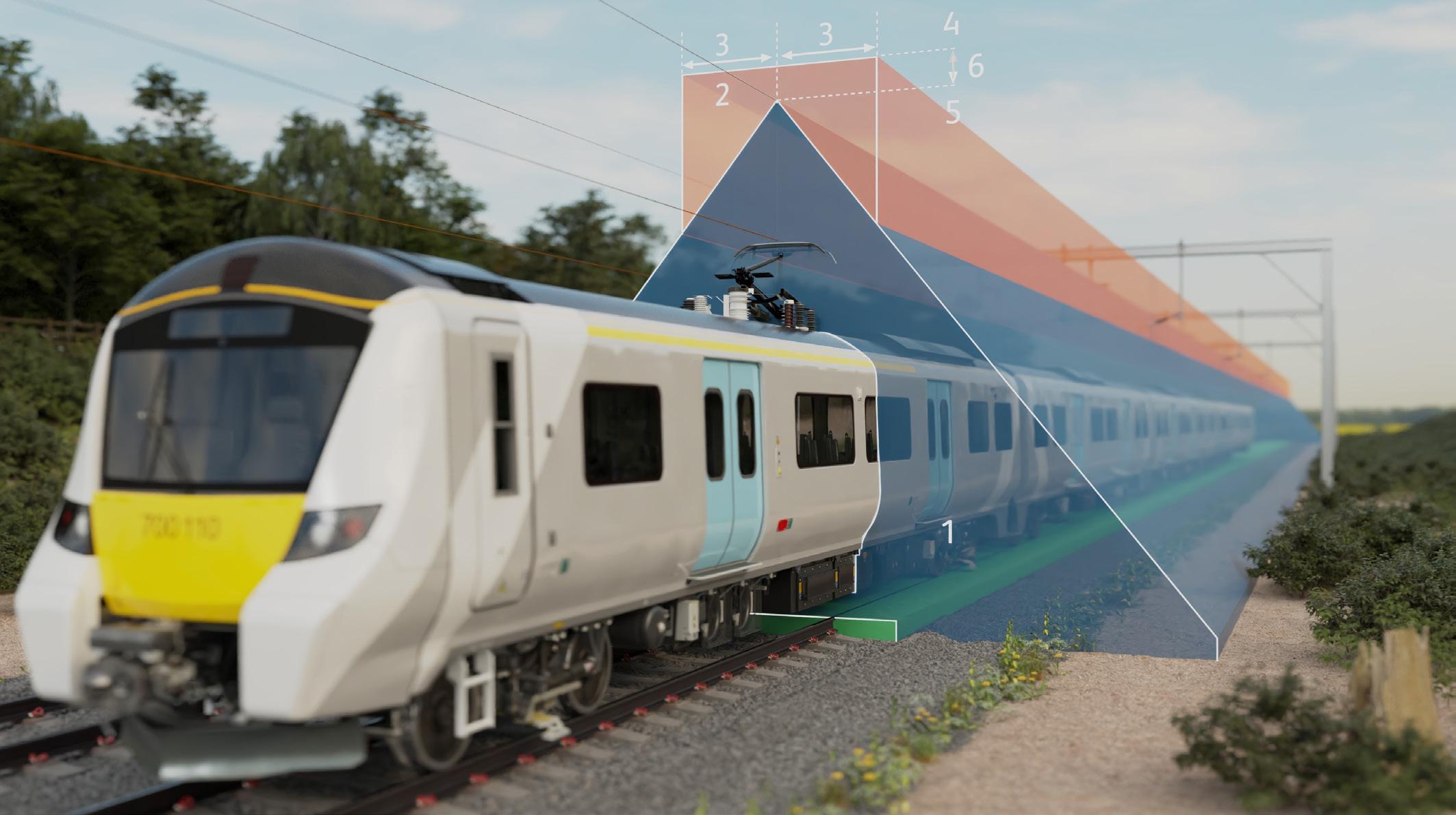
Figure 4. Overhead contact line zone (1) and current collector zone (2).
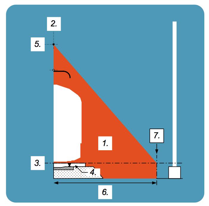
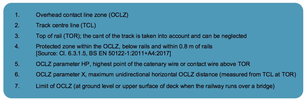
Figure 5: Overhead contact line zone.
LIMITS OF TOUCH VOLTAGE
When a person touches the running rails there will be a voltage between the point of contact and earth. The voltage is based on the current path through the body between hand to both feet or between both hands.
In order to determine whether an impermissible touch voltage can occur, the rail potential along the railway is evaluated for both longterm (operational conditions) and short-term (short-circuit fault or switching) conditions. The long-term (operational conditions) and short-term (shortcircuit fault or switching) voltage limits should not exceed the limits specified in:
a) Effective touch voltage limits (Ute) in BS EN 50122-1 b) Rise of earth potential limits (URE) in i. ENA ER G12 ii. BS EN 50443
The short-term voltage limits (Ute and U
RE) are depicted in figure 2.
For an initial evaluation, the effective touch (Ute) is taken as the rise of earth potential (URE) at the traction return rails. In practice, however, persons touching the rails will not be exposed to the full rise of earth potential. The effective touch voltage limits in BS EN 50122-1 may be recalculated by applying a potential decrease factor to URE. BS EN 50122-1 provides a design procedure for assessment of Ute. The accepted practice in Network Rail (NR/L2/ELP/21085) is to use a maximum value of a = 1.25 for the potential decrease factor.
So:
BS EN 50122-1 requires that for any moment in time the maximum value of Ute shall not be exceeded. For short-term (short-circuit fault) conditions, this means that Ute should not exceed the voltage limits from the moment that the fault occurs to the moment the fault is cleared. The time period between fault detection and fault clearance is dependent upon the operational speed of the protection system and the BS EN 50633 protection reliability method that has been applied.
The BS EN 50633 protection reliability methods are:
M1: Simultaneous independent redundancy M2: Circuit local backup protection M3: Overlapping backup protection M4: Supervision.

Key: HP = hight point of contact lines system, TCL = track centre line, TOR = top of rail
Table 1: illustrative dimensions of OCLZ parameter X (or Xp) based on the 30 degree method.
The operation of M1, M2 or M3 protection should be taken as being part of the correct operation of the protection system and is aligned with the principles BS EN 50122 1.
Figure 3 shows, as a theoretical example, the differing effective touch voltages as a result of differential tripping times for protection schemes with differing fault clearance durations.
The ‘solid blue line’ shows the BS EN 50122-1 Ute voltage limits for a=1. The ‘green Ute trace’ shows a compliant system where Ute is within the permissible limits for the duration of the short-circuit fault, the ‘red Ute trace’ shows a non-compliant system.
DETERMINATION OF PROTECTIVE PROVISION LIMITS – ZONE OF INFLUENCE
The ‘zone of influence’, in which an energised broken contact line or energised broken current carrying collector (pantograph in a.c. systems) can affect the railway is determined by the overhead contact line zone (OCLZ) and the current collector zone (CCZ).
Figure 4 shows the OCLZ and CCZ in relation to the contact line system and pantograph.
Conductive parts and equipment within this zone shall be assessed to determine whether they are located within the OCLZ and/ or CCZ.
The dimensions of the OCLZ are determined by the high point (HP) item 5, figure 5, and OCLZ dimension ‘X’ item 6, figure 5.
The dimension of OCLZ parameter ‘X’ is determined by one of the following methods:
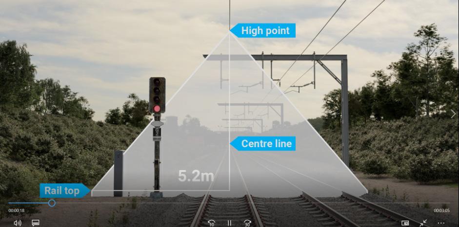
a) X = 5.2 m
(GLRT 1210 Issue 2) b) X = HP × tan 30o m (eqtn. 2) c) X = distance to the OCLS structure (GLRT1210 Issue 2)
Note: method b) currently requires a deviation from GLRT 1210 Issue 2.
Method b is based on experience and over many years on the GB railway, where it has been established that broken parts of the contact line fall within a narrow angle from the track centre line position. The contact line detaches in one of three modes:
1. the contact line detaches with no train present, makes contact with the rail or other parts of the traction return circuit, and initiates a de-energisation of the supply via the protection system 2. the contact line detaches and comes into contact with a vehicle and initiates a de-energisation of the supply via the protection system 3. the contact line detaches and remains energised until coming into contact with a vehicle before initiating a de-energisation of the supply via the protection system. The adoption of the 30-degree method reduces the extent of the OCLZ and therefore reduces the amount of infrastructure and equipment that requires protective provisions (eg by means of bonding).
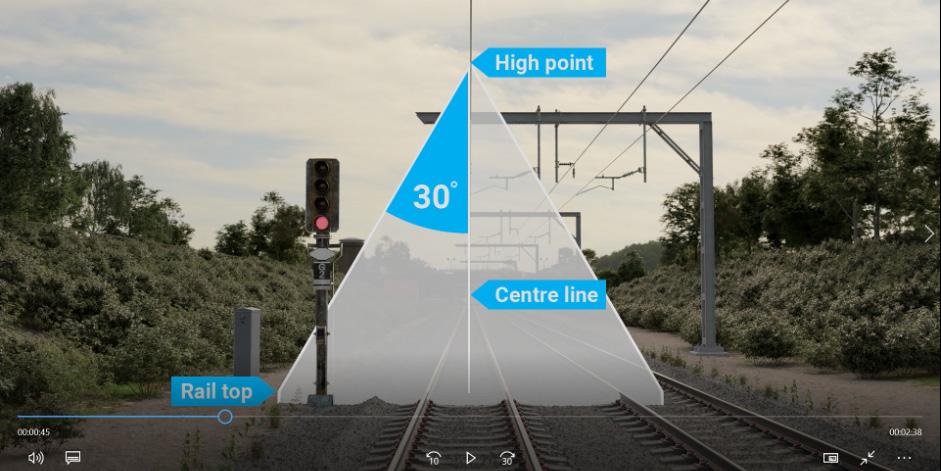
Figures 6a and 6b, taken from an animation scene in the eBriefing module for NR/L2/ELP/21085 illustrate the decrease in the OCLZ extent when adopting the 30-degree method as opposed to the 5.2m method.
Where the ground level is above the top of the rail, as is the case for platforms for example, the dimension for parameter X may be modified. The modified dimension X at platform level (Xp), measured from the track centre line, can be determined as follows:
Xp = (HP – platform height) × tan 30° m (eqtn. 3)
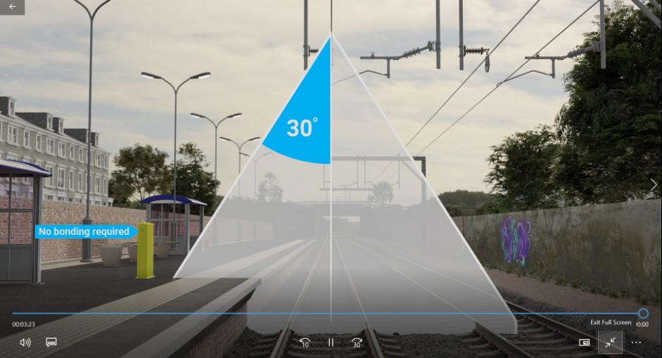
Figure 7, taken from an animation scene in the eBriefing module for NR/L2/ELP/21085 illustrates the OCLZ extent at platform level in station areas.
The table shows that, for the open route railway, the extent of the OCLZ at top or rail level (TOR) can be reduced from 5.2m to be between 3.29m and 4.04m from the track centre line (TCL). As a comparison, the 30-degree method aligns with the BS EN 50122-1 European railways based practice that dimension X to be 4m with a contact system height of 7m.
In station areas, for a standard platform height, the extent of the OCLZ is reduced to be between 2.76m and 3.51m from TCL. In practice the height of the contact line through station areas is reduced, so the 2.76m dimension for the OCLZ extent is likely to be more prevalent.
By way of comparison, figure 8 shows the extent of the OCLZ using the GLRT1210 (5.2m at top of rail, TOR) method and the NR/L2/ ELP/210185 (30-degrees from track centre line, TCL) method. The figure shows that for all contact system heights, for the 30-degree method, the OCLZ is within the area of the platform where buildings, furniture or equipment would normally be excluded.
The reduction in the extent of the overhead contact line zone in station areas, means that there is no requirement to bond some station infrastructure, equipment and low-voltage circuits to the traction return circuit. This has the added benefit of removing or reducing the risk of traction return current being exported either along the railway or outside the railway. Low-voltage circuits in particular benefit, as they can be maintained like any other lowvoltage circuit per BS 7671 (IEE Wiring Regulations).
NR/L2/ELP/21085 EBRIEFING
The NR/L2/ELP/21085 standard is accompanied by an eBriefing multimedia package. Instructions for accessing the eBriefing can be found on the Network Rail Standards site or can be accessed for free via https://learn.networkrail.co.uk/login/index.php
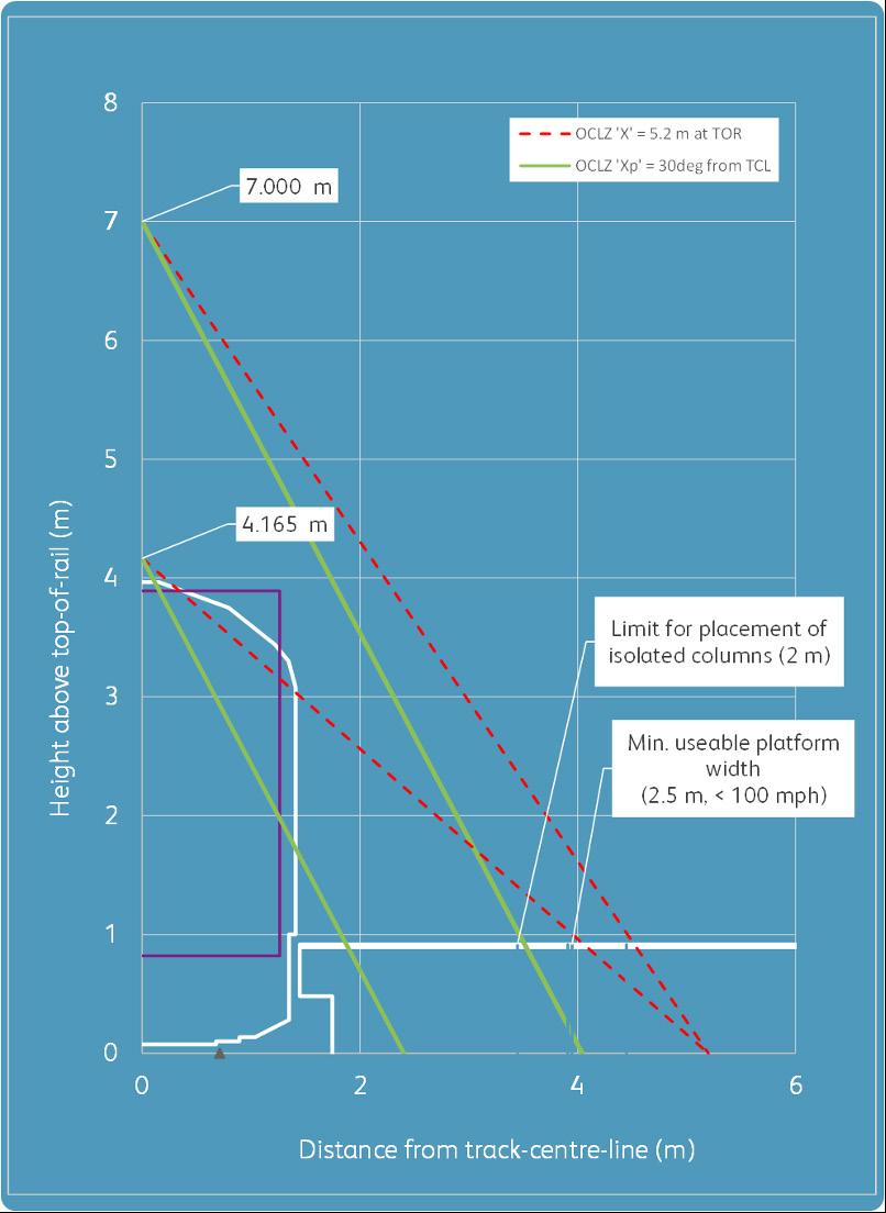
Figure 8: Comparison of OCLZ using GLRT1210 (5.2m at TOR) and 30o from TCL methods.
CONCLUSIONS
The speed and reliability of the protection system plays a vital part in the safe operation of the railway. A fast and reliable protection system will disconnect the supply in the event of a fault and will therefore limit the duration that persons will be exposed to a touch voltage during that time-period. The adoption of protection reliability method M1 ‘simultaneous independent redundancy’ per BS EN 50633 can minimise the time-period between fault initiation and fault clearance. Protection reliability method M1 generally has the fastest fault clearance time compared to other protection schemes.
Provision of a fast and reliable protection system helps the achievement of safe touch voltage limits and supports compliance to Regulations 4.1 and 8 of the Health and Safety at Work Regulations 1989 and mitigates the following key risks:
a) electric shock to members of staff, passengers or public due to direct contact with the traction return circuit, to earthed structural metalwork or equipment under load and fault conditions
b) electric shock to members of staff due to voltage induced into lineside signalling and telecommunications circuits under load and fault conditions
c) electric shock to members of staff due to direct contact with the OCLS or autotransformer feeders under dead conditions
d) electric shock to members of staff due to confusion over Landlord duties under load and fault conditions
e) electric shock to distribution network operator (DNO) staff or members of the public due to voltage exported to other networks, directly under load and fault conditions.
Based on a review of GB experience on the way in which a broken contact line falls, it has been established in the majority of dewirements that the contact line falls within a narrow angle from the track centre line position. NR/L2/ELP/21085 eBriefing.

In NR/L2/ELP/21085 proposes the ‘zone of influence’ caused by a broken contact line is based on the overhead contact line zone (OCLZ) being dimensioned from:
OCLZ parameter X = high point of contact line × tan 30o m For station areas, NR/L2/ELP/21085 proposes that the overhead contact line zone can similarly be dimensioned from:
OCLZ parameter Xp = (high point of contact line – platform height) × tan 30o m
For the open route railway, that the extent of the OCLZ at top or rail level (TOR) can be reduced from 5.2m to be between 3.29m and 4.04m from the track centre line (TCL). The 30o method aligns European practice as provided in BS EN 50122-1 which recommends that OCLZ parameter X = 4.0m.
In station areas, for a standard platform height, the extent of the OCLZ may be reduced to be between 2.76m and 3.51m from TCL. In practice the height of the contact line through station areas is often reduced to clear footbridges etc., so the 2.76m dimension for the OCLZ extent is likely to be more prevalent.
The reduction in the extent of the OCLZ in station areas means that there is reduced requirement for bonding. This has the benefit of removing or reducing the risk of traction return current being exported either along the railway or outside the railway. Low-voltage circuits in particular benefit as they can be maintained like any other low-voltage circuit.
The adoption of the 30-degree method for determining the dimension of the OCLZ realises the possibility of reducing the requirement to provide protective provisions by way of bonding and progress from the de facto position of ‘if in doubt, bond-it-out’. This in-turn has the potential of reducing build costs but also reducing maintenance requirements. The net effect is a tangible and realistic prospect of playing a pivotal financial role in making electrification more financially viable and supports decarbonisation of the railway.