11 minute read
Larkfield to East Kilbride Electrification Project - Through alignment design

by The PWI
Larkfield to East Kilbride Electrification Project (LEKE) - Through alignment design
AUTHOR: Kevin Man BEng
Advertisement
Kevin is a Track Engineer with a BEng in Civil Engineering from the University of Portsmouth. He started his career in Highway and Drainage Construction as a Site Engineer for Natta, then moved onto Highways Design for WSP after graduating before deciding to change disciplines completely and pursue a career in the rail industry as a Track Designer. Kevin now has two years of experience in the Rail Industry in Track Design for WSP working on the Etihad Project, Western and Wales Plain Line Renewals, Greater Manchester Platform Extensions and of course the East Kilbride Electrification Project.
PROJECT OVERVIEW
Currently of the 2776km of rail track in Scotland, only 25.3% (711km) is electrified - The Scottish Government has made major investments into Scotland’s Railway and has committed to a Rolling Programme of Electrification as an initiative to reduce line carbon emissions and improve rail’s green credentials.
It has also been identified by The Scotland Route Study that by the end of Control Period Six (CP6), the number of passengers forecast in the morning peak, on services between Glasgow Central and East Kilbride, will exceed the available seating and standing capacity allowed for the ScotRail franchise.
The scope of the Larkfield to East Kilbride Electrification Project is to support the economic growth in Scotland by providing a rail network in Glasgow Central that can robustly accommodate forecast Passenger demand from the East Kilbride corridor, as an integral part of the Scottish Government’s Rail Services Decarbonisation.
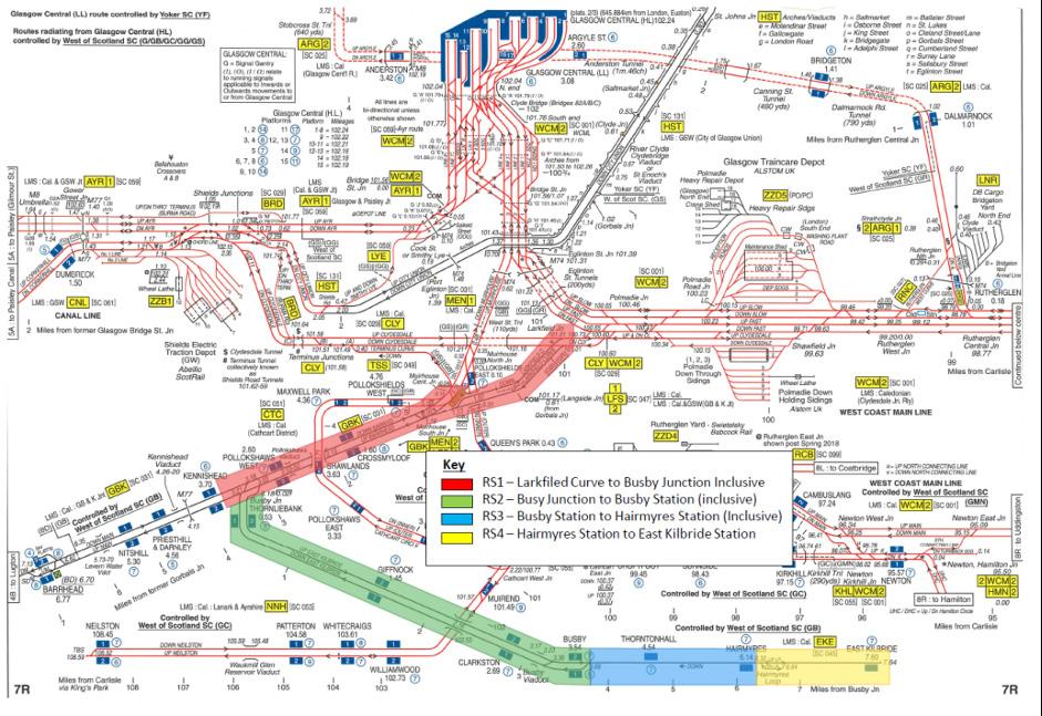
• Providing full electrification of the route, which has been subdivided into 4 Route Sections (see figure 1). • Double tracking on the East Kilbride lines to facilitate the added capacity. • Relocation of Hairmyres station with two platforms. • Platform extension work for all existing stations.
East Kilbride Electrification has developed the Project Feasibility (GRIP 2) Designs into a Multi-disciplinary Option Selection (Grip 3) where a range of track layouts will be reviewed through IDC/IDR and Option Sift Workshops, then through this optioneering process a Single Option Selection (GRIP 4) Multi-disciplinary design will be delivered for each subdivided route, consisting of Horizontal, Vertical and cant track alignments presented in a General Arrangement Drawing and a gauging analysis. The Route Sections have been programmed to be completed in route order from Larkfield Curve to East Kilbride, i.e. Route Section One to Route Section Four, starting with designing the Through Alignments of Route Section One.
EXISTING CLEARANCE ASSESSMENTS
Prior to design, a ClearRoute gauging analysis of the existing structure and vehicle passing clearances was undertaken for all sites - profiles of the structures located within the site limits were created using the topographical survey information; the gauging assessment was undertaken for the structures affected by the proposed design to provide a baseline for a clearance analysis and identify OHLE clearances. A vehicle passing assessment was undertaken based on Project Advice Notice PAN/IP(T)/MI/INS/0062 – Guidance for Civil and Track Project Engineers and Designers, using the range of vehicles listed in the PAN.
THROUGH ALIGNMENT DESIGN
The Through Alignment Design (TAD) aims to provide an aspirational track position that the maintainer can work towards which will ensure a smooth and compliant continuous track alignment throughout the scheme. Once achieved, the TAD track position can be easily reinstated by modern on-track maintenance machinery using the design geometry and computer control. The TAD alignment connects the various intervention sites within the overall electrification scheme and provides smooth easily maintained horizontal and vertical alignments. The adjustments to existing track recognise the need to minimise lifts and slues where possible, especially at overline structures to maximise the existing rail to soffit tolerances.
Achieving sufficient clearance throughout the scheme for Overhead line Equipment (OLE) is one of the main aims for Electrification of the route. The Civils discipline provides support to the OLE design and deliverables by advising on issues that arise and commenting on relevant items including overbridge cross sections for clearance, track lowers affecting structures and any structure modifications and assessments that may be needed as a result of the OLE design.
LARKFIELD CURVE TO CROSSMYLOOF STATION TAD
Larkfield Curve currently provides a generally twin track connecting route between Glasgow and South West Line and the West Coast Main Line. From Muirhouse South junction a short bi-directional section diverges and continues as double track to Larkfield Junction, as shown in figure 2 and described by the sectional appendix extracts in figures 3a and 3b.
The existing Line speed through Larkfield Curve reduces from 40mph to 30mph (figure 3a and 3b). The line speed is used to determine the minimum element length for the Through Alignment Design, as specified in NR/L2/TRK/2102 Issue 10 - Design and Construction of track, where any element less than two seconds of the maximum line speed is considered non-compliant; the design minimum element length through Larkfield Curve would be 35.76m and 26.82 from Larkfield Curve to Crossmyloof Station as shown by the calculation in 1.1.
Minimum Element Length=Distance travelled in 2 seconds at Maximum Line Speed (equation below).
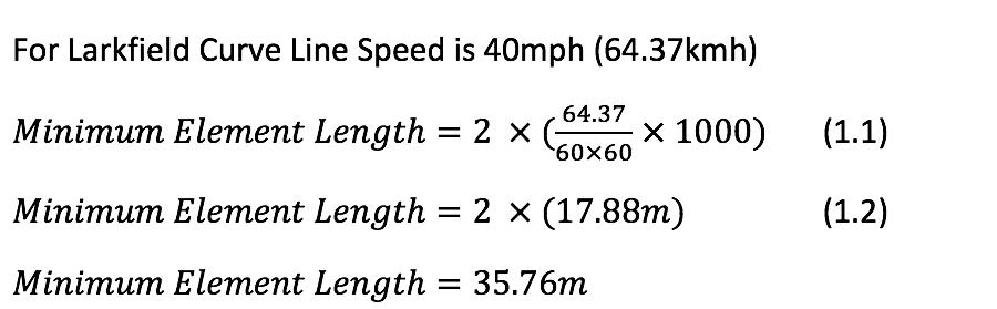
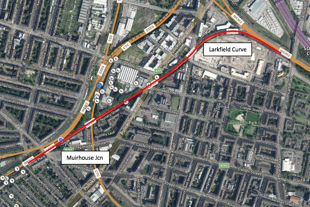
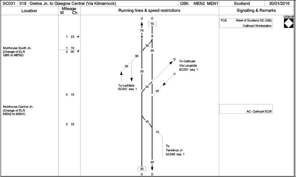
Figure 3a: Route Sectional Appendix Extract of ELR GBK.

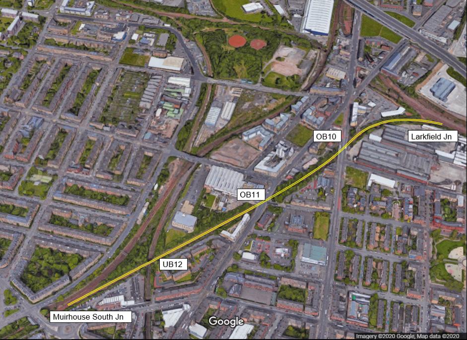
Figure 4: Larkfield curve, Overbridge 10, Overbridge 11 and Miurhouse South Jcn.
From Larkfield Curve to Crossmyloof Station Line Speed ranges from 30mph (48.28kmh) to 70mph (112.65kmh). Using the formula (1.1) we can calculate that the minimum element length for an area of 30mph is 26.82m and 62.58m for 70mph – these minimum element lengths will be used in the horizontal and vertical alignment design.
HORIZONTAL ALIGNMENT DESIGN
To prepare the TAD, the existing track surveyed positions were regressed from a topographical survey using computer software BRT ( Bentley Rail Track) and analysed with the goal of providing a compliant and continuous track alignment – the design started with the Horizontal Alignment to establish the lateral track position and determine where the track would fall relative to the existing infrastructure; the horizontal design is constrained by the width of Overbridges 10 and 11 (figure 4) and the width of the railway cutting, restricting the levels of slews through these particular areas.
A curvature diagram (figure 5a), representing curvature along the path of regression points is produced, and allows identification of which elements make up the existing geometry through interpolating the patterns of the regression points, whilst also identifying the direction and radius of those elements using the vertical axis on the diagram.

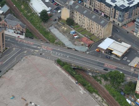
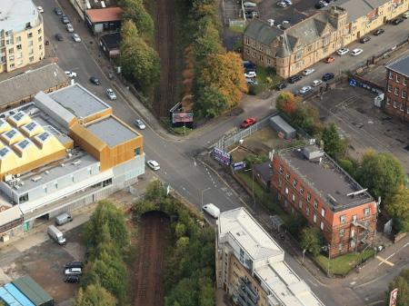
Figure 6a: Overbridge 10 (top), Figure 6b: Overbridge 11 (bottom).
From the curvature diagram, I proposed solutions by placing curves, transitions, and straights through the points of regression that would achieve the least levels of slue where feasible, indicated by the distance between the proposed elements and the regression points – the sporadic arrangement of the survey points has made it so there is no obvious line of best fit to place a compliant element that would achieve minimal slues. Figure 5b shows the proposed solution with larger slews across the transitions connecting the 214.6m radius left hand curve to the 529.81m radius right hand curve with up to a maximum of 212mm slew across Larkfield Curve. Although less than desirable, this track geometry is necessary to achieve minimal slew through the structure Overbridge 10 as to avoid fouling; on this scheme, lifts and slues were required to be less than 75mm across TAD sections only to provide enough clearance for the OLE assets to be installed as part of the Electrification of the scheme.
This constraint also allows for perfect alignment centralisation through structures and avoids infringement with Overbridges 10 and 11 and the sections of narrow cuttings. As a result, this non-compliance exceeding 75mm lift and slue would be documented in the Form A submission for approval by the Regional Engineer.
VERTICAL ALIGNMENT DESIGN
The Vertical Alignment follows the completion of the Horizontal Design and has been described best by Andy Steele as an aim to provide a continuous designed line to smooth the humps and hollows of the survey with long straight gradients and vertical curves, with a view to improve passenger comfort.
The limitations to the vertical design along this TAD alignment have been identified as the structure clearances for the Overbridges and Underbridges located along the alignment, the inter relationship between adjacent tracks especially through Switch and Crossings Units (S&C) where it is critical to achieve coplanarity and the compliance of <75mm lifts and slues as mentioned in the Horizontal design.
Where overbridges are present along the route, the track must be designed to accommodate for passing the overhead line equipment (OLE) under the structure in this electrification scheme; to achieve Efficient Electrification clearances, the OLE along Route Section one requires significant lowering of both tracks at Overbridge 10 and Overbridge 11 by a maximum of 339mm and 787mm respectively since neither structure is able to be raised significantly – as seen in figure 6a and 6b Overbridges 10 and 11 were considered not suitable for re-decking due to their size and because they currently sit beneath busy main roads which would be out of service during reconstruction. As a result, a re-deck was not a viable option and track lowering was advised.
Due to the short distance between the structures and to minimise the number of vertical elements, the proposed design solution extends between and beyond both structures as a single ‘combined’ design vertical profile.
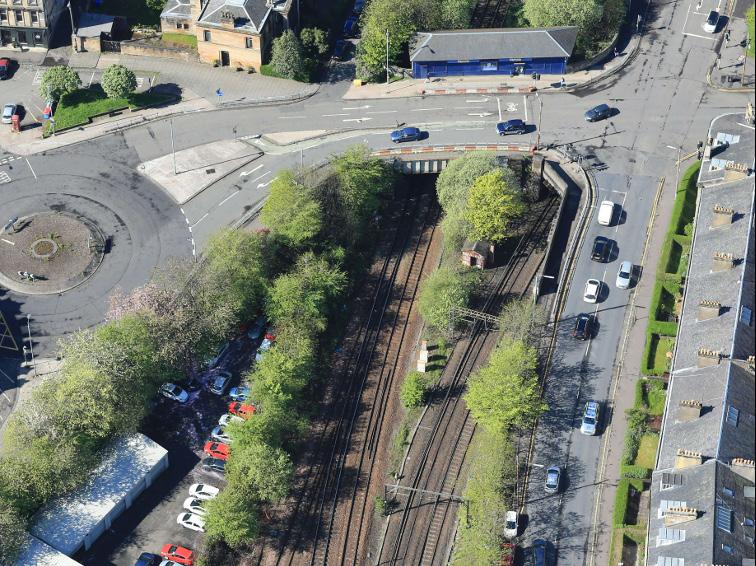
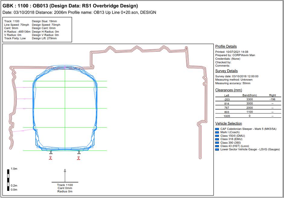
At Overbridge 13 (figure 7) a maximum lift of 390mm is required to rectify the poor vertical alignment and these lifts are contingent on the bridge being renewed to accommodate this alignment, due to its low soffit height, the bridge has been proposed to be re-decked in order to accommodate to proposed track lifts; elsewhere the maximum track lift is circa 50mm.
GEOMETRY PROCEDURES
There are two instances where the horizontal geometry requirements in clause 8.3.1(a) of NR/L2/TRK/2102 have not been achieved (“changes in horizontal alignment shall not be coincidental with changes in Vertical alignment”). In the first instance, to minimise the amount of track lowers throughout the scheme, a vertical curve is proposed which is partly coincident with a horizontal transition element. In the second instance, the large hollow in the existing vertical profile on the approach to the Overbridge 11 is also partly coincident with a horizontal transition.
Removing both these non-compliances would result in significant horizontal track slues which would impact on the proposed abutment design of Overbridge 11 and cutting slope earthworks.
Section 6.7.2 of NR/L2/TRK/2102 (Minimum clearances – track lowering) states “Where concave curves lie below structures then a constant gradient shall be provided beneath the structure and for 30 m each side to maximise the clearance and limit the tendency of on track machines (OTMs) to lift the curve out.”
To reduce the volume of excavated material, a large-radius vertical curve is necessary beneath OB11. In mitigation, adoption of a Managed Track Position strategy will remove the tendency of ontrack machines (OTMs) to lift out the vertical curve and future track maintenance activity would be sufficiently controlled to ensure track position. After establishing a Horizontal, Vertical and Cant design that met the desired criteria, the proposed track geometry was run through Balfour Beatty ClearRoute software for design gauging. This process, as previously mentioned, is an assessment of the track to ensure that vehicles that are used on specific route sections have sufficient spatial clearance and will not be infringed by surrounding structures, lineside equipment, platforms, tunnels, or other vehicles travelling on the adjacent lines.
Multiple overbridges have been identified along the route between Larkfield Curve and Crossmyloof Station including Overbridge 13. The results of the structure clearance gauging can be displayed as a tabulated output or a graphical plot for a visual reference. The worstcase plot as shown in figure 8. indicates that the proposed alignment incurs a foul clearance of up to 203mm on the up track and 202mm on the down track. The Civil Engineering design for the re-deck at Overbridge 13 is based on the rail levels included in this design and the new superstructure.
CONCLUSION
The proposed design aims to be a continuous and compliant alignment that also satisfies client requirements. When it is not possible, clear reasoning must be demonstrated for the noncompliance and the design will be subject to client approval. The Electrification of the scheme requires significant clearances for OLE and as a result may require considerable modifications to existing infrastructure in order to achieve safe clearances. In TAD 1, Overbridge 13 has been identified to require re-decking and Footbridge 13A removed following the gauging analysis due to large foul clearances. When re-decking is not feasible, alternative strategies must be implemented such as the track lowering at Overbridges 10 and 11.
Upon the completion, approval and signing off the GRIP 4 design and the closing out of the Document Review Notices (DRN’s), the Larkfield to East Kilbride Electrification scheme will progress to the Detailed Design stage (GRIP 5) to be completed by another contractor.
REFERENCES
Network Rail. (2021). Living by the Railway - Electrification. Retrieved from Network Rail: https://www. networkrail.co.uk/communities/livingby-the-railway/electrification/
Pajung, K. (2020). HS2 Gauging - The Uniform Structure Gauge (USG). The PWI Journal January 2020.
RouteView. (2021). RouteView. Retrieved from RouteView: www. routeview.visivi.com/nr-routeview/
Scotland’s Railway. (2021, May). East Kilbride Enhancements. Retrieved from Scotland’s Railway: https:// scotlandsrailway.com/projects/eastkilbride-enhancements
Steele, A. (2020). Vertical Alignment Design. Back to Basics.
Transport Scotland. (2021). Electrification Programme. Retrieved from Transport Scotland: https:// www.transport.gov.scot/projects/ electrification-programme/ electrification-programme/