9 minute read
Building Entry Walk


4. Repeat steps 1 through 3 on the opposite wall: draw three arcs, select the edges along the trail and drawn arcs, and activate the From Contour tool to generate a slope. Clean up any artifact geometry. Add color to the simulated terrain.
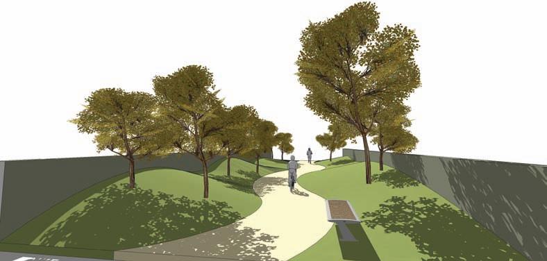
5. Add trees and vegetation to the simulated slopes. Include people, benches, and other amenities to complete the scene. Learn to snap trees and other objects to the sloping surfaces generated in the tutorial.
Advertisement
Building Entry Walk
The goal of this tutorial is to construct a walk and associated terrain leading up to a building entry. This tutorial is more complex than the previous examples using construction geometry. All the edges drafted will be used to define the various slopes and grades. The purpose of the tutorial is to demonstrate how simple edges can be used to generate specific elevations and grades.
Some of the steps for this tutorial can read as complex. Take your time and work through them. The method is relatively easy once complete but requires you to think threedimensionally.
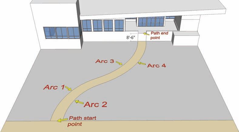
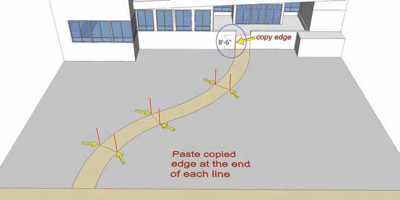
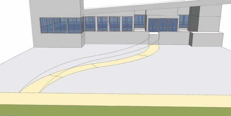
Download from 3D Warehouse and open model: Building_Entry_Walk 1. Identify the areas in the model reviewed in the diagram: the four arcs that compose the walk (two on each side) and the building entry and walk starting point. The building entry is located 8´-6˝ up along the vertical face of the building where the walk ends. You will use the arcs and walk endpoints as references to construct a framework to model the sloping walk and landscape.
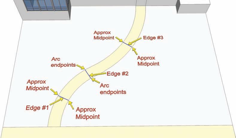
2. Draft three horizontal edges onto the walk, snapping to the arc endpoints and midpoints. These edges will be used in the next step to place vertical edges along the length of the walk.
a. Draft Edge 1 between the approximate midpoints of Arc 1 and Arc 2. Make sure the edge is perpendicular (magenta when being drafted). b. Draft Edge 2 from the endpoint where Arc 1 and Arc 3 connect to the opposite endpoint where Arc 2 and Arc 4 connect. c. Draft Edge 3 at the approximate midpoint of Arc 3 to the midpoint of Arc 4. Make sure the edge is perpendicular.
3. Select, copy, and paste (using Move/Copy) the 8´-6˝ vertical edge at the building entry.
Select one of the vertical edges that flank the building entry. Select the edge at its bottom endpoint. Paste the edge to both endpoints of edges 1, 2, and 3 from the previous step.
The copied edges represent the highest point that the slope needs to reach to achieve the sloping walk.
4. The arcs and edges added in the next steps (4 through 9) are called projected arcs and projected edges. They are the vertical projections of the lines that form the horizontal walk. In essence, you are building a sloping wire frame of the horizontal walk. The projected lines will be snapped to various points along the vertical edges added in step 3.
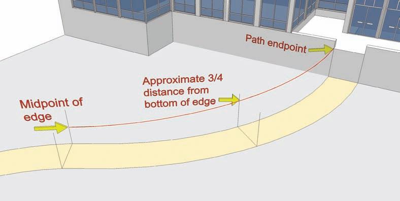
Start with walk arc 3.
a. Using the Arc tool, snap the first point of projected arc 3 to the top of the vertical edge at the building entry. b. Next, snap the second point to the midpoint of the vertical edge where arc 1 connects to arc 3. Snap the bulge (third point) of the arc approximately 3/4 of the way up on the vertical edge at the midpoint of horizontal arc 3.
The diagram shows the intended result. The arc is sloping from the building entry to the mid part of the walk. The projected arc should be located directly above the horizontal arc 3.
Projected arc 3
Horizontal arc 3
5. Copy the two horizontal edges added in step 2 that are connected to horizontal arc 3 upward along the vertical edges. Move/Copy each edge separately. The edges should be snapped to the intersection point of projected arc 3 and the vertical edge. Use the diagram as reference. These copied projected edges will be used as guides to snap to projected arc 4.
Horizontal edge Horizontal edge

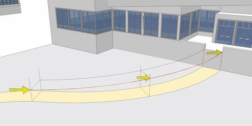
6. Add a second projected arc above horizontal arc 4 . Use the projected edges copied in step 5 as references for the arc snap points and bulge location. Snap the first point of the arc to the top of the building entry opposite projected arc 3. Snap the second point to the endpoint of the projected edge copied upward in step 5 located at the intersection of arc 2 and arc 4.
Snap the bulge to the endpoint of the projected edge located at the midpoint of horizontal arc 4.
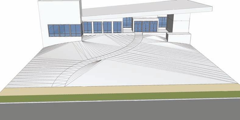
The added projected arc 4 should be parallel to projected arc 3 and directly above horizontal arc 4, as indicated in the diagram. The result: If done correctly, you will have created a simple wireframe composed of edges and arcs. There should now be two sloping arcs sloping from the building entry toward the middle of the walk. The first half of the walk is now complete.
Horizontal arc 4 Projected arc 4
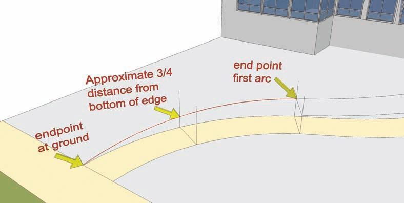
7. Repeat steps 4 through 6 on the lower part of the walk at horizontal arcs 1 and 2, creating projected arcs 1 and 2. a. Start with projected arc 1. Draft an arc, snapping the first point to the endpoint of horizontal arc 1 at the endpoint at ground. Snap the second arc point to the endpoint of the projected arc 3. b. Snap the arc bulge approximately 3/4 of the way down from the top of the middle vertical edge located at the midpoint of horizontal arc 1. With projected arc 1 complete and connected to projected arc 3, one side of the walk frame is complete.
Projected arc 1 Projected arc 3
Horizontal arc 1
8. Move/Copy upward the horizontal edge located at the midpoints of horizontal arcs 1 and 2. Snap the copied edge to the intersection of projected arc 1 and the vertical edge the arc bulge was snapped to.
Add projected arc 2. This is similar to step 7. Snap the first point of the arc to the endpoint of horizontal arc 2 at the start of the walk. Snap the second point to the endpoint of projected arc 4. Last, snap the bulge to the endpoint of the projected edge copied and placed in this step.
Horizontal arc 2 Projected arc 2 Projected arc 4

9. Delete all the projected and vertical edges. Do not delete any of the arcs.
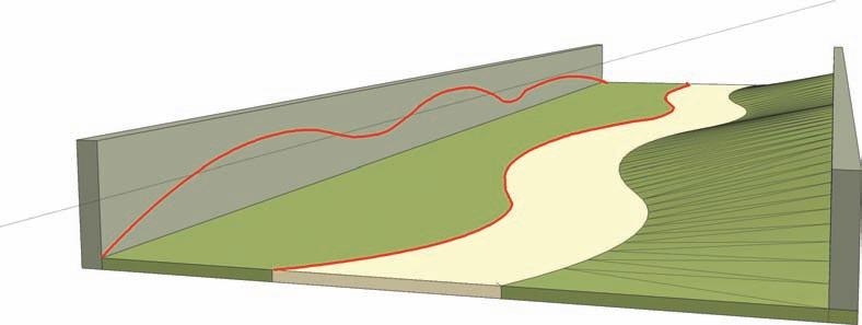
The resulting construction geometry consists of four connected, sloping arcs that parallel the walk underneath. The projected arcs now provide a realistic, sloping path from the start of the walk to the building entry.
The next steps are similar to the Slopes and Grades tutorial. A series of edges and arcs will be drafted on the vertical faces of the building. This will help further define the future grades that will define the Building Walk Entry.
10. Draft a series of connected arcs on the vertical surfaces of the building. Starting with the surfaces to the left of the walk, begin at the location where projected arc 3 connects to the building entry. There will be a total of three arcs on three faces. The last arc should connect to the bottom, outside endpoint of the building (where it intersects the ground). Follow the diagram for the relative heights and placement of these arcs.
Projected arc 3 Projected arc 4

11. Next, starting at the intersection of projected arc 4 at the building entry and moving to the right, draft another series of connected arcs on the vertical surface of the building. As with step 10, there is a total of three arcs, with the last arc connecting to the bottom of the building where it intersects the ground. Make sure to follow the diagram to achieve the heights and placement of the arcs.
Projected arc 4

12. It’s time to generate the walk and grade surfaces. Select all the edges as indicated in the diagram. Select all the edges drafted in steps 4 through 11. Include the outer bottom edges of the ground that runs parallel to the entry walk. With all the edges selected, activate From Contour.
13. The From Contour tool will generate a sloped trail and terrain leading to the building entry. Toggle on Hidden Geometry (View > Hidden Geometry). You can see all the faces that From Contour generated to create the slopes and walk. However, color is needed to help define what is a walk surface and what should be landscape. The next steps will demonstrate how to add color.

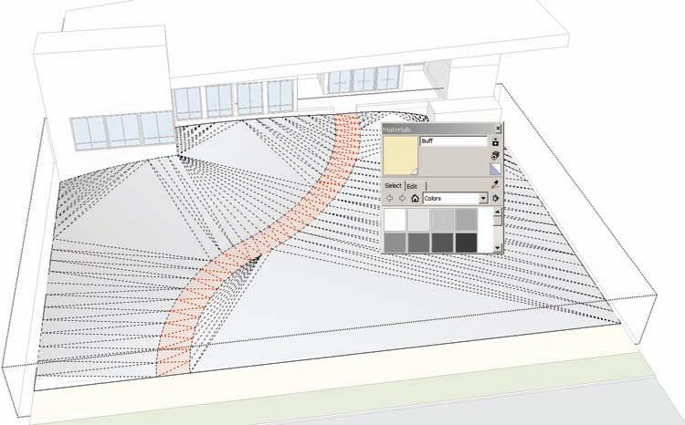
14. Enter the group instance of the generated slope creating by using From Contour. Select all the faces that compose the walk. The outside arcs of the walk will be clearly visible. Use the Select tool and hold Ctrl to create an additive selection. Try using the selection box to select the correct faces. Hidden Geometry must be toggled to visible for this work.
15. With the faces of the path selected, apply a Marker > Beige color from the Materials palette to the faces. Exit the component instance and apply a lawn (green) color to the slope group. This will paint the remaining surfaces. Toggle Hidden Geometry to off.
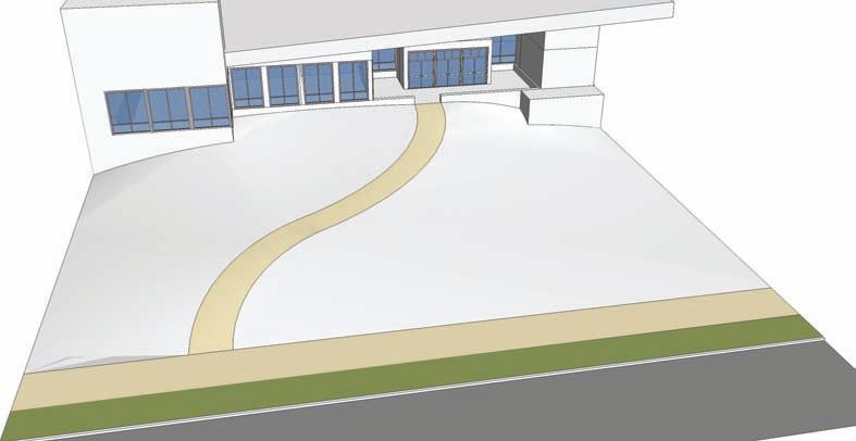
The sloping entry walk and terrain are completed. While there are other advanced methods to achieve the same goal, using construction geometry allows you to measure the rise and run of a particular walk, grade, or elevation to create greater precision. This is useful when designing accessible ramps or to gain an understanding of what specific slopes are part of a project model.
16. Add trees, cars, people, pedestrian lights, bike racks, and other amenities to the walk and grades to make the scene more realistic.


