2 minute read
Detailing the Planters


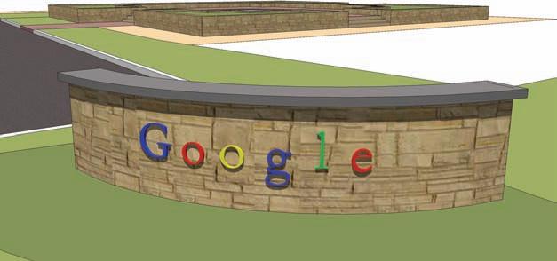
e. Once all the letters are placed, turn off Hidden Geometry (View > Hidden
Geometry). f. Add color to each letter (Fig. 7-46).
Advertisement
Fig. 7-46: Add color to the 3D text.
Detailing the Planters
The Scale tool can help you model existing geometry to create irregular shapes. In this example, you’ll use it to create sloped walls. 1. Select only the top face of one of the smaller planter walls. a. Activate the Scale tool. Because the face is flat (2D), only eight green scale handles will appear. Ctrl+Alt and select a corner green handle and push it inward. This will accomplish two things (Fig. 7-47): The face will be uniformly scaled 33 inward on all sides.
The vertical wall faces will fold inward with the scaled top surface, creating a sloped 33 wall (Fig. 7-48).
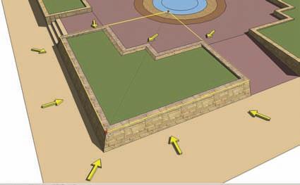
Fig. 7-47: Scale the top face of wall inward to create a sloped surface.
Fig. 7-48: The sloped vertical faces of the planter wall.

2. Go to the next small planter wall. Select the top face and repeat step 1. This time, select a corner green handle and push it outward (Fig. 7-49). The walls’ vertical faces will fold outward with the scaled top surface (Fig. 7-50).
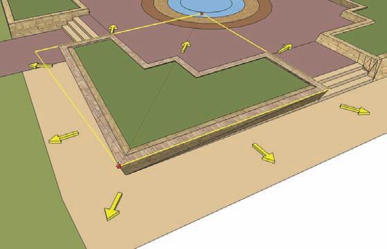
Fig. 7-49: Scale the top face of the wall outward to create a levered wall.

Fig. 7-50: The levered vertical faces of the wall.
Although this method adds detail, it does create some problems with the geometry around the walls. Locations where the wall faces are attached or are sticking to other geometry, such as the steps, will contain irregular geometry (Fig. 7-51). This is unavoidable; fortunately, irregular geometry can be masked. While holding the Shift key, use the Eraser tool and select the irregular edges. This will hide the lines.
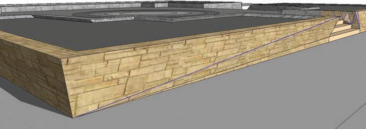
Fig. 7-51: Hide any irregular geometry created when you scale the top wall faces.
When you finally generate images or animations of models with any such irregular geometry, avoid focusing on those areas. Instead, focus your images where the sloped walls appear clean and calculated.
Now that the various elements and surfaces have been added and detailed, the Flatwork Base is finished (Fig. 7-52). Make sure to save the model for use in later chapters and tutorials. The next step for the site plan model is to populate and arrange pre-made and custom components.

Fig. 7-52: The completed and detailed Flatwork Base and volumes.


