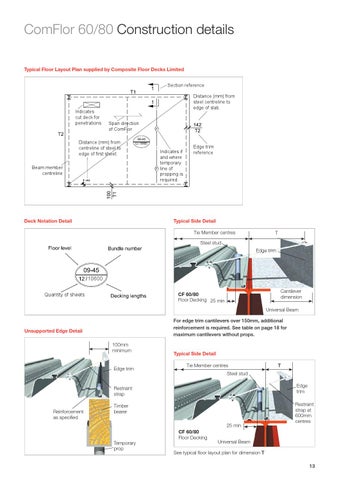
ComFlor 60/80 Construction details Typical Floor Layout Plan supplied by Composite Floor Decks Limited Section reference
Indicates cut deck for penetrations
Distance (mm) from steel centreline to edge of slab. Span direction of ComFlor
Distance (mm) from centreline of steel to edge of first sheet. Beam member centreline +94
10600
Indicates if and where temporary line of propping is required.
Edge trim reference
Typical Side Detail
Deck Notation Detail
Tie Member centres
T
Steel stud Edge trim
10600 Cantilever dimension
CF 60/80 Floor Decking 25 min
Quantity of sheets
Universal Beam For edge trim cantilevers over 150mm, additional reinforcement is required. See table on page 18 for maximum cantilevers without props.
Unsupported Edge Detail 100mm minimum
Edge trim
Typical Side Detail Tie Member centres
Edge trim
Restraint strap Reinforcement as specified
Timber bearer 25 min Temporary prop
T
Steel stud
CF 60/80 Floor Decking
Restraint strap at 600mm centres
Universal Beam
See typical floor layout plan for dimension T 13