plate locks
dual ejection application
Stripper
Gauge Pin: .500” or 14mm Dia.
Gauge Pin: .500” or 14mm Dia.
T
Release Point “T”= Stripper Stripper Plate Travel + .212 (6.66mm)
Release Point “T”=
Plate T Stripper • Utilize Plate Locks for keeping both ejector sets together until preset release point. Travel + .212 .001 (.03mm) • Machine all pockets as shown Gap onbetween the previous page, mounting the Guide Assembly/Wedge Block in the bottom Ejector Plate. (6.66mm) Driver Cap & Wedge Block Required
.001 (.03mm) Gap between Driver Cap & Wedge Block Required
plate locks
stripper plate application
Provided Length = 7.5”
Provided Length = 7.5”
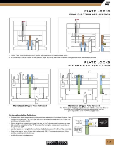
Mold Closed: Stripper Plate Retracted
Mold Open: Stripper Plate Released The Drivers push the stripper plate forward until the parts are stripped from the core. The lock then releases, allowing the ejector pins to push the parts from the stripper plate.
Design & Installation Guidelines: • Stripper plate applications can be utilized as shown above with the optional Stripper Plate Kit as sold on page J-4. The Latch Bar will be discarded and replaced with the Driver, Cap, and Spacer offered in the kit. • All pocket and component machining is similar to the 3-plate application shown on page J-2 except for calculation of the “T” dimension for timing the release point according to the graphic at right. • Use the Spacer as a template for machining the bolts/dowels on the Driver/Cap assembly. • Attach the Spacer to the Driver, which will provide .03”/.75mm gap between the Driver and the mold to avoid interference. • Install all components as shown.
Stripper
Gauge Pin: .500” or 14mm Dia.
T
T = Initial Plate release - .212” (6.66 mm)
.001 (.03mm) Gap between Driver Cap & Wedge Block Required
J-3