//SYS21///INTEGRA/BST/VOL2/REVISES 31-7-2001/BSTC11.3D ± 450 ± [427±472/46] 30.7.2001 3:48PM
450 Basic ship theory
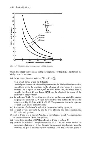
Fig. 11.11 Variation of harmonic pressure with tip clearance
trials. The speed will be stated in the requirements for the ship. The steps in the design process are now: l
(a) thrust power in open water TV1 PT T lR T
M
from which thrust T can be deduced; the designer assesses an allowable pressure on the blades if serious cavitation e ects are to be avoided. In the absence of other data, it is recommended that a ®gure of 80 kN=m2 be used. From this, the blade area to provide the thrust T, and hence BAR can be obtained in terms of the diameter of the propeller; (c) for values of BAR, for which methodical series data are available, deduce the propeller diameter D. We can now illustrate the method to be used by reference to Fig. 11.5 for a BAR of 0.65. The procedure has to be repeated for each BAR under consideration; (d ) for a series of values of J, calculate the corresponding r.p.m., n; (e) for each n value calculate KT and by cross plotting ®nd the corresponding P=D ratio and value; (f) plot n, P and to a base of J and note the values of n and P corresponding to the maximum . Note this value; (g) repeat for a number of BARs and plot n, P and to base D; (h) read o the values at the optimum value of D. This will either be that for maximum e ciency or, if this diameter is too great, the diameter must be restricted to give a satisfactory tip clearance from the vibration point of