//SYS21///INTEGRA/BST/VOL1/REVISES 21-7-2001/BSTC06.3D ± 195 ± [177±236/60] 26.7.2001 4:18PM
The ship girder 195
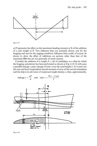
Fig. 6.17
at P represents the e ect on the maximum bending moment at X of the addition of a unit weight at P. Two in¯uence lines are normally drawn, one for the hogging and one for the sagging condition. In¯uence lines could, of course, be drawn to show the e ect of additions on sections other than that of the maximum BM but are not generally of much interest. Consider the addition of a weight P, x aft of amidships, to a ship for which the hogging calculation has been performed as shown in Fig. 6.18. It will cause a parallel sinkage s and a change of trim t over the total length L. If A and I are the area and least longitudinal second moment of area of the curved waterplane and the ship is in salt water of reciprocal weight density u, then, approximately, sinkage s
Fig. 6.18
uP A
and
trim t
P x
f uL I