//SYS21///INTEGRA/BST/VOL1/REVISES 21-7-2001/BSTC06.3D ± 183 ± [177±236/60] 26.7.2001 4:18PM
The ship girder 183
Fig. 6.7 Approximate hull weight distribution
B U O Y AN C Y AN D B AL AN C E
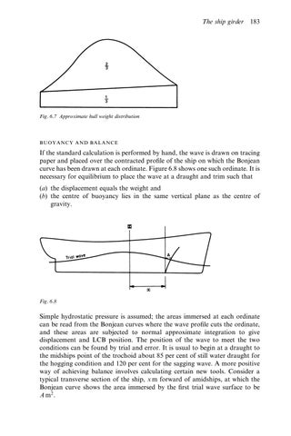
If the standard calculation is performed by hand, the wave is drawn on tracing paper and placed over the contracted pro®le of the ship on which the Bonjean curve has been drawn at each ordinate. Figure 6.8 shows one such ordinate. It is necessary for equilibrium to place the wave at a draught and trim such that (a) the displacement equals the weight and (b) the centre of buoyancy lies in the same vertical plane as the centre of gravity.
Fig. 6.8
Simple hydrostatic pressure is assumed; the areas immersed at each ordinate can be read from the Bonjean curves where the wave pro®le cuts the ordinate, and these areas are subjected to normal approximate integration to give displacement and LCB position. The position of the wave to meet the two conditions can be found by trial and error. It is usual to begin at a draught to the midships point of the trochoid about 85 per cent of still water draught for the hogging condition and 120 per cent for the sagging wave. A more positive way of achieving balance involves calculating certain new tools. Consider a typical transverse section of the ship, x m forward of amidships, at which the Bonjean curve shows the area immersed by the ®rst trial wave surface to be A m2 .