17 minute read
Your pipe supports are causing expansion joint failures


Feature Your pipe supports are causing
expansion joint failures By: CJ Horecky, Executive Director, INTEREP Inc.
Plant maintenance personnel frequently come to INTEREP asking if we can “quote a new expansion joint, like this one, ASAP.” I like the challenge of a 72-hour turnaround on engineered equipment just as much as the next guy, but most of the time a “new expansion joint, like this one” isn’t going to last a whole lot longer than the previous one did. Ours might have better weld procedures or thicker materials, but if it’s designed to handle the same movements as the last one did, and the movements in your system have changed, it’s also going to prematurely bite the dust. Often, your expansion joint is failing due to your pipe supports. Keep reading, perhaps you’ll consider adding one simple annual inspection to your plant’s routine to have a consistent read on the overall health of your piping and ducting system.
Here’s one you can probably walk out and find in your plant today: pipe or duct slide plates
that are no longer functioning as originally intended. It’s a common issue—the slide plate that has slowly built-up corrosion, debris, or even successive layers of paint, until the drag coefficient on the two interfacing surfaces became so high that the piping began to look elsewhere for a softer spot to move.
If not that scenario, perhaps you’re the proud owner of some PTFE-lined slide plates. This is an excellent technology. PTFE is effectively acid-proof, it’s somewhat abrasionresistant, and should last years between replacements. But how do you know when that replacement time has come? A quick visual inspection of these, like that of the brake pads on your car, should show you how thick the remaining PTFE is, whether it’s still anchored tightly into the support (not loose, angled, missing, etc.) and what sort of path it’s been traveling (based on abrasion marks on the sole plate). If they aren’t properly maintained, your slide plates become anchors, which usually results in significant increases in axial movement experienced by your expansion joints down the line, and thus fail prematurely.
Another often-overlooked issue that causes supports and anchors to act in ways never intended by their designers stems from tall posts or structures beneath the support in question. You’ve frequently seen piping systems elevated above process areas for a handful of reasons related to process, safety, or traffic-flow. This introduces a new challenge: leverage. A tall post (say, 15 feet or greater) beneath a support or saddle will bend or deflect far easier (in fact, 50% easier, leverage is a linear formula) than a 10-foot post will. Add to that a cantilever (arm) coming off the post to support a run of pipe or duct, and it adds up to a critical situation. Even sliding supports can cause deflection or torsion on the cantilevered post beneath them. Once that occurs, you have a low point in your piping, or new angular movements being exerted by the bent or torqued support. This travels down the line and eventually ends up in your expansion joints as either angular or lateral movement. If your expansion joints were designed for axial-only, and you’ve added angular or lateral movements to them, you now have concurrent movements and may have just decimated their lifespan.
Slide plates aren’t the only candidate for routine annual inspection. Their equal-and-opposite counterparts, piping restraint hardware, can cause some real damage as well. For similar reasons to those already stated, restraining hardware is designed to control movements in a predictable fashion. When not properly maintained, they will often introduce new movements into a system, and ultimately the expansion joints.
I promise to stop mentioning slide plates after this, but just let me beat one last, unexplored area of this horse: slide plate guides. Guides are restraining hardware; they keep any sliding supports moving in an axial-only or lateral-only direction. They are usually welded to the sole plate in the form of two strips of steel. Check annually to ensure these are present and accounted for. (There should never be just one guide; they always come in pairs.) If the welds on these guides corrode or break, or the guides that were once present are no longer, you’ve got movements in your system that it wasn’t designed to take—and you’ve likely compromised an expansion joint somewhere down the line.
More readily recognizable as restraints are large, cross-vessel or cross-duct braces. These often appear in the form of turnbuckles, tie-rods, huge pieces of angle, flat bar, or other metals in tension between two points on a system. These exist primarily to counterbalance pressure-thrust forces between pipes, ducts, or vessels. If you’ve established an annual maintenance routine for these braces complete with photo documentation, consider yourself way ahead of the game. These restraints will frequently experience turbulence from system vibration, wind-chatter across them (think rachet straps on a tied-down truck load), and general thermal growth and shrinkage. There is a proper schedule for torquing them, but I’m guessing it was either never delivered by the EPC, or it’s been lost to history. So, the next best thing? Develop a spreadsheet of the critical cross-vessel restraints to keep an eye on, perform an annual photo inspection, and make sure these restraints are pulling on the two vessels, ducts, or pipes that they are designed to keep in tension. In case you need a little extra motivation, this one isn’t just about your expansion joints, it’s about the entire vessel. If you have two towers tied together with an expansion joint between them, and the cross-vessel restraints slacken over time, an unrestrained expansion joint that was formerly putting kips of pressure-thrust into the vessel nozzle only is now putting that force into the entire vessel. Now imagine the expansion joint is 75 feet off the ground. (Remember that bit about leverage we looked at earlier?) You may be inching toward a tower collapse.
You can’t talk about pipe supports without talking about spring hangers, cans, supports, etc. We’ll just call them devices that are designed to allow a specific amount of movement in a system without any friction, via the use of springs. You probably know a lot about these already. They’re simple. Unfortunately, you likely have several hundred of these in your plant and you might have several thousand. Here’s where you’re probably going to want to hire an inspections intern who will do nothing but walk around an inspect spring supports; or you’re going to want a third party like INTEREP to take over the task.
Spring supports often experience problems due to corrosion, especially when acid is present. The problem is it’s hard to see the corrosion due to the shielded nature of the spring assembly. When a spring corrodes, either locking up or letting loose, it causes the movements in the piping attached to it to deviate from design. In a straight run of pipe going into an expansion joint, this will result in angular or lateral movement being introduced and can significantly decrease the lifespan of the joint (as if I haven’t mentioned that enough already).
Even more common than corrosion is improper adjustment and maintenance of spring supports. These parts fall into a bit of a no-man’s land: an inspector finds something funny on a spring can, tells the maintenance person, and then maintenance doesn’t want to mess with it without checking with operations. Operations then asks if anything is leaking, maintenance says “no,” and the group decides to leave it wellenough alone. Spring supports appear to have a lot going on. There are dials, gauges, different colored markers, some kind of bars sticking out from the spring, and tiny notes and diagrams on the side. In reality, they’re just like all of your other equipment, and there are experts out there who will have no problem giving your field crews a quick run-down on the dos and don’ts of inspection and adjustment. Just hang onto this one little inspection tip: if you’re seeing high spots in your piping, chattering in lines at startup, cracks in piping, or premature expansion joint failures, try checking the spring supports.
Less often noticed, and harder to correct, is the important issue of spring support spacing. You’d be safe to assume that your system was designed for the number of spring supports it currently has, and you probably don’t want to mess with it by adding more. In a perfect world, that would be entirely correct, but we just went over a whole bunch of reasons that new movements are added to piping systems unintentionally. With these new movements come new variables for your existing spring support system to cope with. INTEREP customers have sometimes found themselves in the unfortunate position of needing more spring support architecture in their system, but not wanting to screw things up any worse by adding them. A good way to know if you have too few spring supports is to watch for pooling in your piping system (low spots, sagging) which will usually result in condensate buildup, mineral chokepoints, or corrosion on the bottom of piping or ductwork. This, like everything else, can also result in accelerated degradation of your expansion joints.
Do you have more questions than you started with? I can offer a little more important advice. Consider implementing an annual inspection plan that documents your slide plates, restraint hardware, and spring supports. Keep a running spreadsheet with tag numbers for each component, hot and cold measurements, and pictures. This will save you more headaches than it causes you. There you have it. That’s our secret inspection plan. Now either do it yourself or engage someone like INTEREP to come do it for you.
Stop buying new expansion joints like-inkind. If they’re failing every two years, you’ve got issues elsewhere. I’d wager that it has something to do with new movements introduced by your slide plates, anchors, guides, restraints, or spring supports. And it can be fixed. By performing a three-day annual inspection, you will reveal critical unknowns that give you a clear picture of what is causing your problems and where it is, you’ll be able to catch issues before they become failures, and ultimately, you’ll increase your plant’s uptime and your own peace of mind.
For more information, please visit www. interepinc.com or email CJ Horecky at cjh@ interepinc.com. q
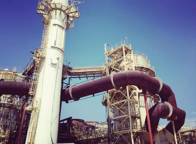
Tall ductwork supports combined with expansion joints in a sulfuric acid plant.
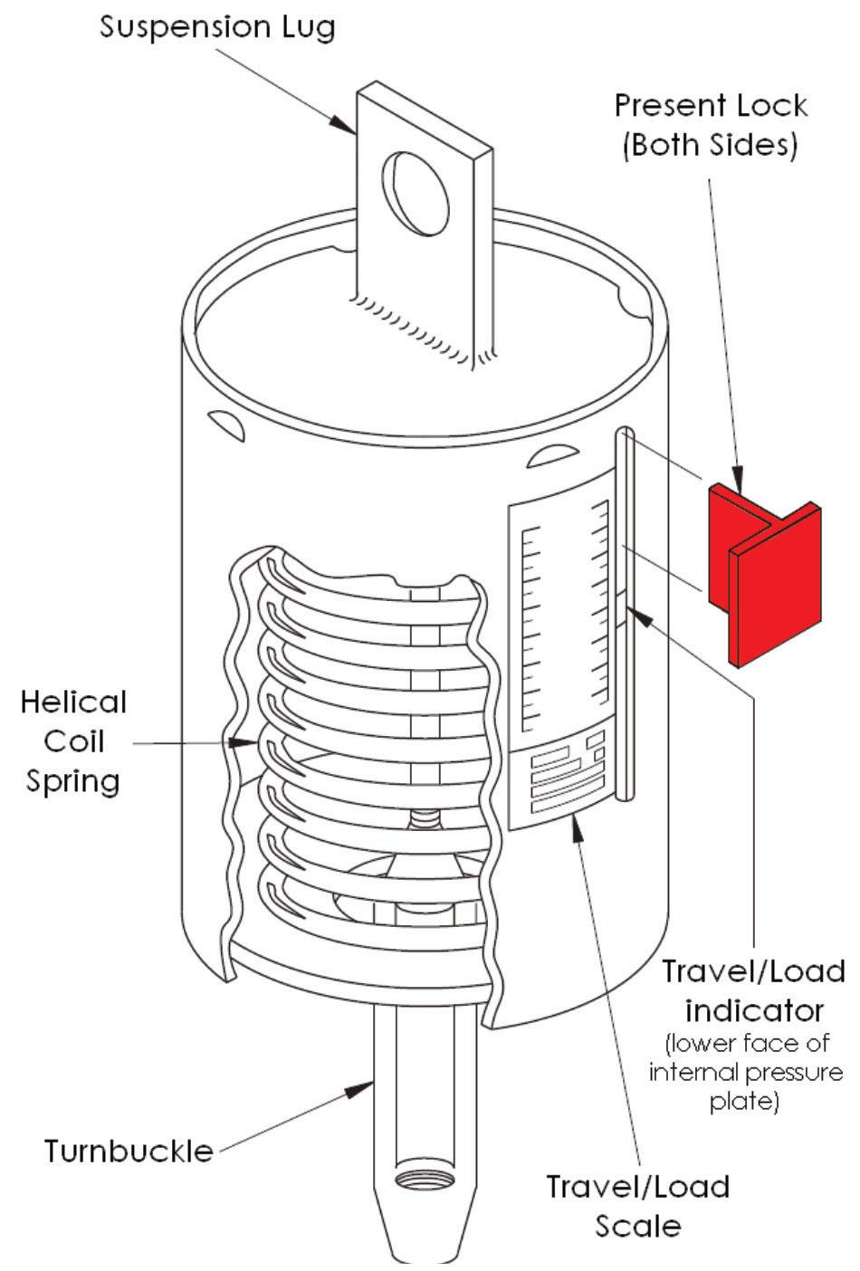
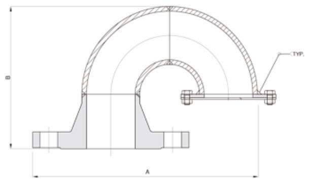
The basic components of a variable spring can “hanger” support.
Department LESSONS LEARNED: Case histories from the sulfuric acid industry
Storage tank vent control
By: W. M. Weiss, MECS® Technologies, subsidiary of Elessent Clean Technologies
Storage tanks are often overlooked pieces of process equipment – assumed to be little more than wide spots in the line. The storage tank is an operating piece of equipment with level indication and often some kind of vent control. The storage tank vents may contain hazardous compounds and often need to be contained and directed to recovery/abatement equipment. In this article, we will discuss vent containment needs for fresh and alkylation spent sulfuric acid tanks.
Fresh acid storage tank vents
Fresh acid storage tanks or product acid tanks normally range in concentration from 93.0 wt% to 99.2 wt%. Balance is water with minor amounts of impurities. The stored liquid is by and large colorless and odorless. Temperature is near ambient or slightly above, normally coming directly from production at 104oF (40oC) or less.
Tank material of construction is normally carbon steel with some higher alloys in specific areas of the tank nozzles and internal pipes. Corrosion rates are low and tank life of 30 years or more is common. But to the extent that corrosion does occur, hydrogen generation is occurring simultaneously. Top vented storage tanks allow the hydrogen to escape as needed and allow the tank to breathe. Tanks operate at atmospheric pressure and will “inhale” when the vapor space is cooled with changes in weather or when tank levels are reduced. Tanks will “exhale” during tank filling or heating of the vapor space.
Rate of level increase or decrease is most dramatically affected by pump-in rates from production or pump-out rates to loading or other processes. It is common for the level of the storage tank to change significantly over time with changes in production needs.
A gooseneck style vent is usually used atop the tank to allow this breathing. It is mounted high on the tank dome and is open to atmosphere. A bird screen is advised to prevent animals or debris from entering the vent and causing flow restriction. A free-flowing vent will allow for hydrogen dispersion and prevent over-pressure or vacuum that can damage the tank. Sizing of the gooseneck is based on the anticipated maximum fill rate and extraction rate from the tank.
An option to using an open vent is to provide air inlet dryers. Air contains atmospheric humidity. The acid on the tank walls and top layer of the stored liquid will readily absorb this moisture. The dryer assembly is often a static piece of equipment that uses a desiccant to remove the majority of the moisture from the air prior to entering the storage tank. In time, the desiccant becomes saturated and must be changed out. The dryer may also pose a flow restriction – especially when it is dirty. Any flow restriction may not adequately disperse the hydrogen and may allow vacuum or pressure build-up beyond the tank design specifications. These dryers are not common in the US but are more commonly observed in Africa and Europe.
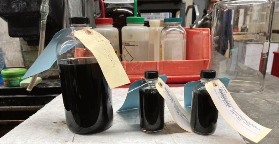
Fresh sulfuric acid sample.
Alkylation spent acid storage tank vents
Spent sulfuric acid comes in many forms. Alkylation spent acid is quite well defined. Other spent acids from chemical processes can vary a great deal in their make-up, so there may be a great variation in what may be present in the tank vents. This section focuses on spent acid from refinery alkylation processes.
Typical alkylation spent acid is quite consistent from site to site and in simple form is described as follows:
Sulfuric acid: 89 – 91 wt%
Hydrocarbon: 3 – 6 wt%
SO2: trace
Water: balance
Temperature: ambient or slightly below
The acid is opaque and black in color due to the hydrocarbon content. It is odoriferous – containing some SO2 gas as well as hydrocarbons.
Hydrocarbon description is generic and in practice is made up of many different cyclic hydrocarbons and some organic sulfates. Reaction may continue within the storage tank, and this makes for heavier molecular weight organic compounds over time and may release SO2 gas on a continuous basis. Long term polymerization of these compounds may result in a fluid that is difficult to handle. It becomes gooey. Long term storage is not preferred. Removal of the hydrocarbon layer from time to time is also preferred.
As in fresh acid storage, tank material of construction is normally carbon steel with some higher alloys in specific areas of the tank nozzles and internal pipes. Corrosion rates are low and tank life of 30 years or more is common. But to the extent that corrosion does occur, hydrogen generation is occurring simultaneously. Top-vented storage tanks allow the hydrogen to escape as needed and allow the tank to breathe. Tanks left to their own control operate at atmospheric pressure and will “inhale” when the vapor space is cooled with changes in weather or levels are reduced. Tanks will “exhale” during filling or heating of the vapor space. Different from the fresh acid storage tanks is that the breathing is controlled with blanket gas and one or more vent destinations. Rarely do these storage tanks vent directly to atmosphere for an extended period.
The density of the hydrocarbon layer is about one third that of the acid layer. Separating into distinct layers is common, and the top inventory of the tank is an organic rich layer. Storage tanks in this service are often equipped with skimmers or taps along the side wall of the tank for hydrocarbon layer removal. Lighter organics will be present in the vapor phase. This is a combustible environment if exposed to air. Fires in spent acid storage tanks have occurred. Complete loss of the storage tank can be the result. Hence, an inert gas blanket is used to keep the tank somewhat above atmospheric pressure and relatively free of oxygen.
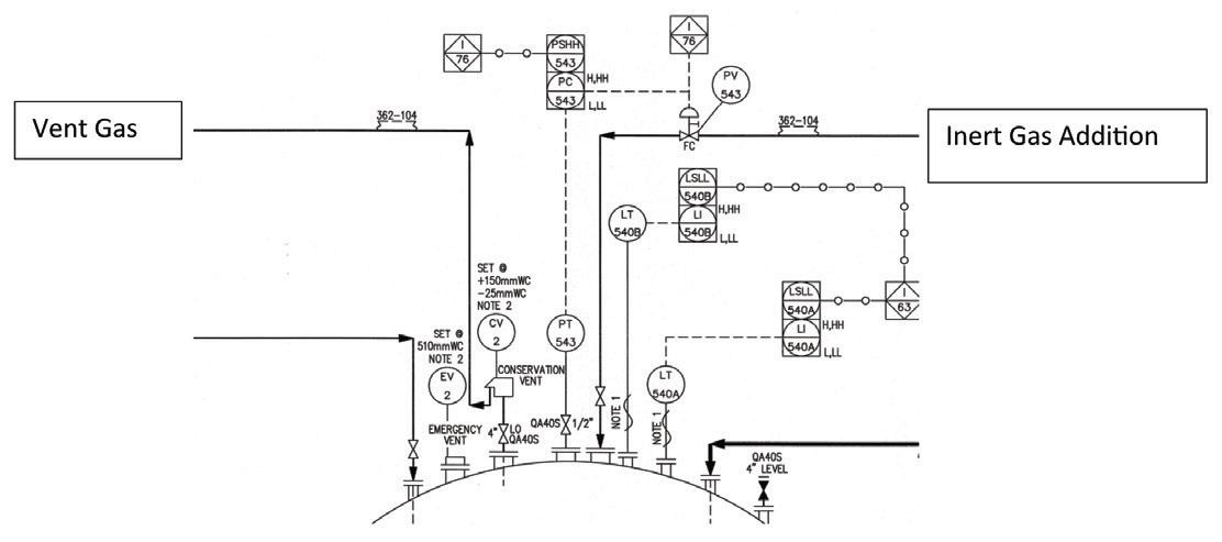
Tank pressure is controlled at a set point ranging between atmospheric pressure and the tank design pressure (which is important to know). As the pressure falls below set point, inert gas flow (normally this is nitrogen) is automatically opened to the tank to maintain the pressure. As the pressure rises above set point, the nitrogen flow is stopped. As it continues to rise, a second (higher) pressure set point allows the tank vent to open. An example: • Tank design pressure: 10 in wc (255 mm wc) • Tank vent valve opens: 6 in wc (150 mm wc) - form of a conservation vent • Nitrogen addition valve opens: 3 in wc (75 mm wc) – form of a control valve
In this example, between 3 and 6 in wc, the tank pressure is allowed to float. Process control action only occurs when the measured pressure deviates between the two pressure set points. With lower pressure than this specified range, the nitrogen is added. Higher pressure than this range, venting occurs.
The tank is protected from loss of pressure control in that the conservation vent will allow air ingress at vacuum conditions and an emergency door is provided in case of overheating (i.e. external fire in the tank farm). API provides guidance as to sizing of this opening. The emergency door is often a weighted hatch which swings open upon high pressure but will not reseat automatically – it needs to be returned to the closed position manually. Set point will be somewhat below the design pressure of the storage tank. The pressure indicator/controller is provided with alarms at high and low pressure which need to be investigated by the field operators. Maybe the emergency door is not fully closed.
During normal operation, the vent gas is often fed to the spent acid decomposition furnace – directly through a shell opening. There is normally inadequate gas pressure to feed this through the burner assembly. Flash back in the vent piping is prevented at the combustion chamber with the use of a flame arrestor. If this is moved upstream in the piping for improved maintenance access, then the use of a detonation flame arrestor is preferred.
During shutdown of the acid plant, the tank continues to vent. If allowed by local authorities, the plant may vent to atmosphere for a short period of time. If short term atmospheric venting is not allowed, a secondary means of abatement is required. This secondary means could be a flare or ground flare or could be a caustic scrubber with carbon canisters for hydrocarbon removal. Some use the scrubber and carbon canisters as primary abatement and avoid the connection to the furnace altogether.
A schematic of the spent acid tank pressure control.
Tank farm operation
Most operating spent acid regeneration plants, and maybe the refinery alkylation unit as well, will employ three storage tanks or more. Tanks can be manifolded together in different fashions to allow operating flexibility: • Fresh acid storage of 98 – 99 wt% • Option for alternate fresh acid storage of weaker acids – either for additional acid products or for off-spec acid (maybe from startup) that can be worked off with normal production acid over time • Spent acid storage • Swing tank that can store fresh acid or spent acid depending on inventory needs
The swing tank is designed and treated as a spent acid tank with inert gas capability and venting to an abatement system. This vent control need not be used if always in fresh acid service. But normal plant protocol dictates that once this storage tank is placed in spent acid service, the tank is viewed as a spent acid storage tank from that point forward.
For more information, please visit www. MECS.ElessentCT.com or email Walter Weiss at Walter.Weiss@ElessentCT.com q