structural REPAIR Novel Solution for Strengthening Handrail Anchorage By Ali Abu-Yosef, Ph.D., P.E., S.E., Joseph Klein, P.E., Michael Ahern, P.E., and Randall Poston, Ph.D., P.E., S.E., NAE
D
esign and detailing of handrail anchorages in concrete structures must consider both structural performance
and susceptibility to corrosion. Without these dual considerations, handrail anchorages are more likely to fail. For decades, premature corrosion of handrail anchorage components was prevalent in the concrete industry. Deterioration of the anchor embedments due to galvanic corrosion, direct exposure of aluminum to concrete, or insufficient concrete cover resulted in costly repairs. While improvements in structural detailing and material selection to mitigate corrosion have been successfully implemented and are now common practice, the structural design and installation of handrail anchorages remains a minefield. A primary cause of continued handrail anchorage issues is the lack of clear delineation of design responsibilities and detailed coordination between the architect, handrail system manufacturers, the engineer of record, and the contractor. As a result, inappropriate assumptions and poor communication remain a source of deficient handrail installations. Repair of structurally deficient rail-post anchors is both challenging and costly. Rail-post anchorage repairs often must maneuver tight geometries, a concrete substrate congested with steel reinforcement, numerous forms of potential corrosion cells, and elevated access limitations. This article presents a novel repair solution that was used to address structurally deficient handrail anchorages in a high-rise building. The repair approach presented herein uses inert materials that are not susceptible to corrosion due to environmental exposure.
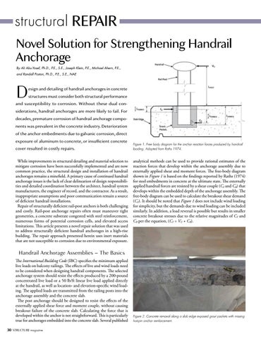
Figure 1. Free body diagram for the anchor reaction forces produced by handrail loading. Adapted from Raths 1974.
analytical methods can be used to provide rational estimates of the reaction forces that develop within the anchorage assembly due to externally applied shear and moment forces. The free-body diagram shown in Figure 1 is based on the findings reported by Raths (1974) for steel embedments in concrete at the ultimate state. The externally applied handrail forces are resisted by a shear couple (CF and CB) that develops within the embedded depth of the anchorage assembly. The free-body diagram can be used to calculate the breakout shear demand (CF). It should be noted that Figure 1 does not include wind loading for simplicity, but the demands due to wind loading can be included similarly. In addition, a load reversal is possible but results in smaller concrete breakout stresses due to the relative magnitudes of CF and CB per the equation, (CF = VU + CB).
Handrail Anchorage Assemblies – The Basics The International Building Code (IBC) specifies the minimum applied live loads on balcony railings. The effects of live and wind loads need to be considered when designing handrail components. The selected anchorage system should resist the effects produced by a 200-pound concentrated live load or a 50 lb/ft linear live load applied directly at the handrail, as well as location- and elevation-specific wind loading. The applied loads are transmitted from the railing posts into the anchorage assembly and the concrete slab. The post anchorage should be designed to resist the effects of the externally applied shear force and moment couple, without causing breakout failure of the concrete slab. Calculating the force that is developed within the anchor is not straightforward. This is particularly true for anchorages embedded into the concrete slab. Several published 30 STRUCTURE magazine
Figure 2. Concrete removal along a slab edge exposed grout pockets with missing hairpin anchor reinforcement.