

combined bending and torsion stress is maximum, ftorsion = Torsional warping stress at location in cross-section where combined bending and torsion stress is maximum. Eq. (1) enables one to accommodate situations where the maximum stress due to combined bending and torsional warping occurs at the tip of a flange stiffener, and at web-flange or flange-lip junctions.
e) Section D3.3, Bracing of Axially Loaded Compression Members . The
Designation
AISI S100-12
revised provisions should produce a more reliable and economic design of bracing to a compression member because the brace force and stiffness are now calculated based on the axial load in the column. The required brace force and stiffness can also be determined using the frame analysis that takes into consideration second-order effects (i.e., considering both P- and P-∆ effects).
Title
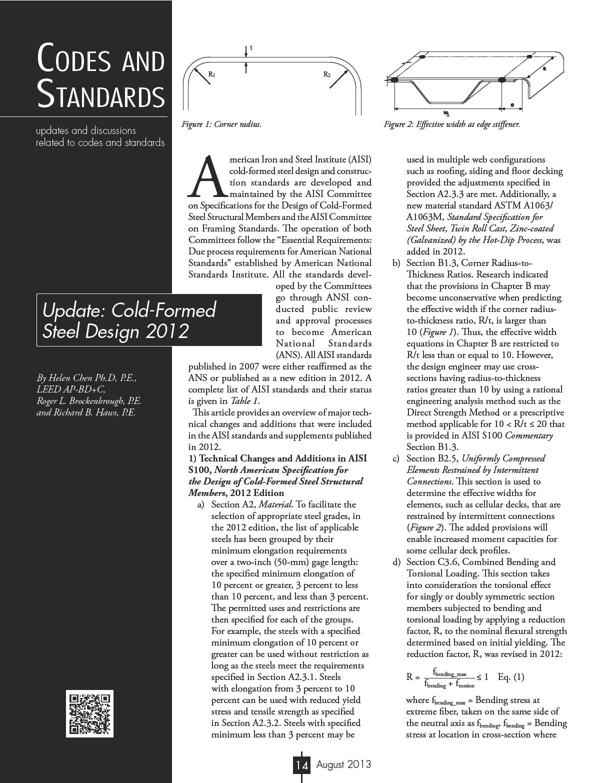
f) Section E3, Bolted Connections. Provisions are added to determine the strength of bolted connections for slotted or oversized holes. The slotted or oversized hole sizes are defined in AISI Table E3a. The bearing strength, Pn, without consideration of bolt hole deformation can be determined from: Pn = C mf d t Fu Eq. (2) where C = Coefficient determined in accordance with AISI S100 Table
North American Specification for the Design of Cold-Formed Steel Structural Members, 2012 Edition
AISI S110-07w/S1-09 (2012)Standard for Seismic Design of Cold-Formed Steel Structural Systems-Special Bolted Moment Frames with Supplement 1, 2007 Edition (Reaffirmed 2012)
AISI S200-12
AISI S201-12
AISI S202-11
AISI S210-07w/S1 (2012)
North American Standard for Cold-Formed Steel Framing – General Provisions, 2012 Edition
North American Standard for Cold-Formed Steel Framing – Product Data, 2012 Edition
Code of Standard Practice for Cold-Formed Steel Structural Framing, 2011 Edition
North American Standard for Cold-Formed Steel Framing – Floor and Roof System Design with Supplement 1, 2007 Edition (Reaffirmed 2012)
AISI S211-07 (2012) North American Cold-Formed Steel Framing – Wall Stud Design, 2007 Edition (Reaffirmed 2012)
AISI S212-07 (2012) North American Cold-Formed Steel Framing – Header Design, 2007 Edition (Reaffirmed 2012)
AISI S213-07 w/S1-09 (2012)North American Standard for Cold-Formed Steel Framing – Lateral Design with Supplement 1, 2007 Edition (Reaffirmed 2012)
AISI S214-12
AISI S220-11
North American Standard for Cold-Formed Steel Framing – Truss Design, 2012 Edition
North American Cold-Formed Steel Framing – Nonstructural Members, 2011 Edition
AISI S230-07 w/S3 (2012)North American Cold-Formed Steel Framing – Prescriptive Method with Supplement 3 (Reaffirmed 2012)
AISI S901-08
AISI S902-08
AISI S903-08
AISI S904-08
Rotational-Lateral Stiffness Test Method for Beam-to-Panel Assemblies, 2008 Edition
Stub-Column Test Method for Effective Area of Cold-Formed Steel Columns, 2008 Edition
Standard Methods for Determination of Uniform and Local Ductility, 2008 Edition
Standard Test Methods for Determining the Tensile and Shear Strength of Screws, 2008 Edition
AISI S905-08 w/S1-11Test Methods for Mechanically Fastened Cold-Formed Steel Connections with Supplement 1, 2008 Edition
AISI S906-08
AISI S907-08
AISI S908-08
AISI S909-08
AISI S910-08
AISI S911-08
AISI S912-08
AISI S913-08
AISI S914-08
Standard Procedures for Panel and Anchor Structural Tests, 2008 Edition
Test Standard for Cantilever Test Method for Cold-Formed Steel Diaphragm, 2008 Edition
Base Test Method for Purlins Supporting a Standing Seam Roof System, 2008 Edition
Standard Test Method for Determining the Web Crippling Strength of Cold-Formed Steel Beams, 2008 Edition
Test Method for Distortional Buckling of Cold-Formed Steel Hat Shaped Compression Members, 2008 Edition
Method for Flexural Testing Cold-Formed Steel Hat Shaped Beams, 2008 Edition
Test Procedure for Determining a Strength Value for a Roof Panel-to-Purlin-to-Anchorage Device Connection, 2008 Edition
Test Standard for Hold-Downs Attached to Cold-Formed Steel Structural Framing, 2008 Edition
Test Standard for Joist Connectors Attached to Cold-Formed Steel Structural Framing, 2008 Edition
E3.3.1-1; mf = Modification factor for type of bearing connection determined according to AISI S100 Table E3.3.1-2; d = Nominal bolt diameter; t = Uncoated sheet thickness; and Fu = Tensile strength of sheet as defined in AISI S100 Section A2.1 or A2.2.
g) Section E3.4, Shear and Tension in Bolts. The nominal tensile and shear strengths of bolts were updated to be consistent with the values in the AISC Specification.
h) Section E4.5, Combined Shear and Tension. This section now includes three combined shear and tension checks for screw connections: combined shear and pull-over, combined shear and pull-out, and screw combined shear and tension, where combined shear and pull-out and combined shear and tension are newly added:
For combined shear and pull-out:
For ASD Eq. (3) and
For LRFD Eq. (4)
where Q, Qu, and T, Tu = Shear and tension forces, respectively, determined in accordance with ASD or LRFD load combinations; Pns = Nominal shear strength of sheet per fastener = 4.2(t32d)1/2Fu2; and Pnot = Nominal pull-out strength of sheet per fastener = 0.85tcdFu2; Ω = Safety factor = 2.55; φ = Resistance factor = 0.60; t2 =Thickness of member not in contact with crew head or washer, Fu2 = Yield stress of t2; d = Nominal diameter of screw; and tc = Lesser of
• Wind Analysis for Tornado and Hurricane Based on 2012 IBC Section 423 & FEMA 361/320.
• Mitigate Lateral Drift for Cantilever Column using Post-Tensioning.
• Moment Connection Design for Beam to Weak Axis Column Based on AISC 360-10.
Coupon for Package: $120 off Code: ASCE 7-2010
AISI S100 Table E3.3.1-1 Bearing Factor, C
Thickness of connected part, t, in. (mm)
0.024 ≤ t < 0.1875 (0.61 ≤ t < 4.76)
Connections with standard holes
Ratio of fastener diameter to member thickness, d/t C
Connections with oversized or short-slotted holes
Ratio of fastener diameter to member thickness, d/t C
Note: Oversized or short-slotted holes within the lap of lapped or nested Z-members as defined in AISI Section E3 are permitted to be considered as standard holes.
AISI S100 Table E3.3.1-2 Modification Factor, mf, for Type of Bearing Connection
Type of Bearing Connection
Single Shear and Outside Sheets of Double Shear Connection using Standard Holes with Washers under both Bolt Head and Nut
Single Shear and Outside Sheets of Double Shear Connection using Standard Holes without Washers under both Bolt Head and Nut, or with only One Washer
Single Shear and Outside Sheets of Double Shear Connection using Oversized or Short-Slotted Holes Parallel to the Applied Load without Washers under both Bolt Head and Nut, or with only One Washer
Single Shear and Outside Sheets of Double Shear Connection using ShortSlotted Holes Perpendicular to the Applied Load without Washers under both Bolt Head and Nut, or with only One Washer
Inside Sheet of Double Shear Connection using Oversized or Short-Slotted Holes Parallel to the Applied Load with or without Washers
Inside Sheet of Double Shear Connection using Short-Slotted Holes Perpendicular to the Applied Load with or without Washers
Note: Oversized or short-slotted holes within the lap of lapped or nested Z-members as defined in AISI S100 Section E3 are permitted to be considered as standard holes.
depth of penetration and thickness of t2. The equations are applicable with the following requirements satisfied:
(1) 0.0297 in. ≤ t2 ≤ 0.0724 in., (2) No. 8, 10, 12, or 14 self-drilling screws with or without washers, (3) Fu2 ≤ 121 ksi, and (4) 1.0 ≤ Fu/Fy ≤ 1.62. For screw combined shear and tension:
For ASD and
For LRFD
where Pts = Nominal tension strength of screw as reported by manufacturer or determined by independent
laboratory testing; Pss = Nominal shear strength of screw as reported by manufacturer or determined by independent laboratory testing;
Ω = Safety factor = 3.0; and φ = Resistance factor = 0.5.
i) Section E5, Power Actuated Fasteners Comprehensive design equations were adopted for the design of connections using power actuated fasteners. Although the design equations address potential limit states such as shearing of the sheet or the connector, tension pull-over of the sheet or tension pull-out of the fastener, manufacturer’s published design values are still permitted.
j) Appendix 1, Design of Cold-Formed Steel Structural Members Using the Direct Strength Methods. By using
A/S/ S230, Supplement 3, Table A1-3
Conversion of ASCE 7 Basic Wind Speeds to AISI S230 Basic Wind Speeds (mph) 1
ASCE 7-10 Basic
Wind Speed 110115126139152164177190
AISI S230 Basic
Wind Speed 8590100110120130140150
1 ASCE 7 permits linear interpolation between the contours of the basic wind speed maps.
software, Appendix 1 provides a rational engineering analysis approach for determining strengths of cold-formed steel members. Provisions were added for members with holes, web shear strength and inelastic reserve capacity.
2) Technical Changes in AISI S20012, North American Standard for Cold-Formed Steel Framing-General Provisions, and AISI S201-12, North American Standard for Cold-Formed Steel Framing-Product Data
These two standards were reorganized as part of a code synchronization effort to eliminate duplications and redundancy, as well as to clear any ambiguities among AISI and ASTM standards, and building codes. Specific areas considered include: material thickness, physical dimensions and tolerance, mechanical properties, coatings-corrosion resistance, and labeling requirements. Another major reorganization was due to the development of a new AISI S220, North American Standard for Cold-Formed Steel Framing – Nonstructural Members. The design provisions related to nonstructural members were moved from AISI S200 and AISI S201 to AISI S220. Consequently, AISI S200 and AISI S201 are written for structural members, while AISI S220 is specifically for nonstructural members.
3) Technical Changes in AISI S214, North American Standard for ColdFormed Steel Framing – Truss Design
The major change for this standard is related to the provisions of truss responsibilities. Those provisions were extracted from AISI S202, Code of Standard Practice for ColdFormed Steel Structural Framing, and added to AISI S214.
4) Technical Changes to AISI S211, North American Standard for Cold-Formed Steel Framing – Wall Stud Design
Supplement 1 to AISI S211 includes updates of the referenced standards, and deletions of the provisions related to nonstructural members.
5) Technical Changes to AISI S230, Standard for Cold-Formed Steel Framing – Prescriptive Method for One and Two Family Dwellings
With the introduction of ASCE 7-10, an equivalent wind load table was added in Supplement 3 that converts ASCE 7-10 basic wind speeds to AISI S230 basic wind speeds.
6) AISI S220, North American Standard for Cold-Formed Steel FramingNonstructural Members
To help clearly delineate and eliminate confusion between the requirements for cold-formed steel structural members and nonstructural members, AISI S220 was developed in 2011 specifically for the design and installation of cold-formed steel nonstructural members in buildings. AISI S220 should be able to eliminate the confusing industry reference to “equivalent” or “EQ” sections if all nonstructural profiles are designed and designated in accordance with AISI S220. In addition, AISI S220 clarified the definition of nonstructural member as “A member in a steel-framed system that is not a part of the gravity load resisting system, lateral force resisting system or building envelope.”
Examples of a nonstructural members include, but are not limited to, members in a steel framed system which is limited to a transverse (out-of-plane) load of not more than 10 lb/ ft2, a superimposed axial load, exclusive of sheathing materials, of not more than 100 lb/ft, or a superimposed load of not more than 200 pounds. The strength of the nonstructural members may be determined by either non-composite or composite design approach. The non-composite assembly design approach utilizes the design provisions of AISI S100 but with adjusted safety and resistance factors, ΩN = 0.9Ω; and φN = 1.1φ; where Ω, φ = Safety and resistance factors from relevant section of AISI S100; and ΩN, φN = Corresponding safety and resistance factors for nonstructural members. The non-composite assembly design approach can also be done via testing and, with the test results, evaluated
in accordance with AISI S100 Chapter F but with a target reliability index, β0 = 1.6. For composite assembly design approach is generally accomplished by testing and, with the test results, evaluated in accordance with AISI S100 Chapter F. Detailed discussion on nonstructural design and installation can be found from a separate paper, Design of Nonstructural Members in Accordance with AISI S220, by R. A. LaBoube, et al (February 2013, STRUCTURE magazine).▪
Helen Chen, Ph.D, P.E., LEED AP-BD+C, is manager of the Construction Standards Development of the American Iron and Steel Institute. She is directly involved in the development and update of AISI construction standards. Helen may be reached at hchen@steel.org
Roger L. Brockenbrough, P.E., is President of R. L. Brockenbrough & Assoc., Chairman of the AISI Committee on Specifications for the Design of ColdFormed Steel Structural Members, Emeritus Member of the AISC Committee on Specifications, and a member of ASTM. He is the editor of two current McGraw-Hill texts: Structural Steel Designer’s Handbook and Highway Engineering Handbook. Roger may be reached at rogerlbrock@msn.com.
Richard B. Haws, P.E., is manager of Nucor Building Systems, Chairman of AISI Committee on Framing Standards and Vice Chairman of AISI Committee on Specifications for the Design of ColdFormed Steel Structural Members. Richard may be reached at rick.haws@nucor.com.
NEW VERSION RELEASED FLOORVIBE v2.10
Software to Analyze Floors for Annoying Vibrations
• Calculations follow AISC Design Guide 11 Procedures
• Analyze for Walking and Rhythmic Activities
• Check floors supporting sensitive equipment
• Graphic displays of output
• Data bases included
• Expert advice in real time
Demo version at FloorVibe.com
Structural Engineers, Inc.
tmmurray@floorvibe.com
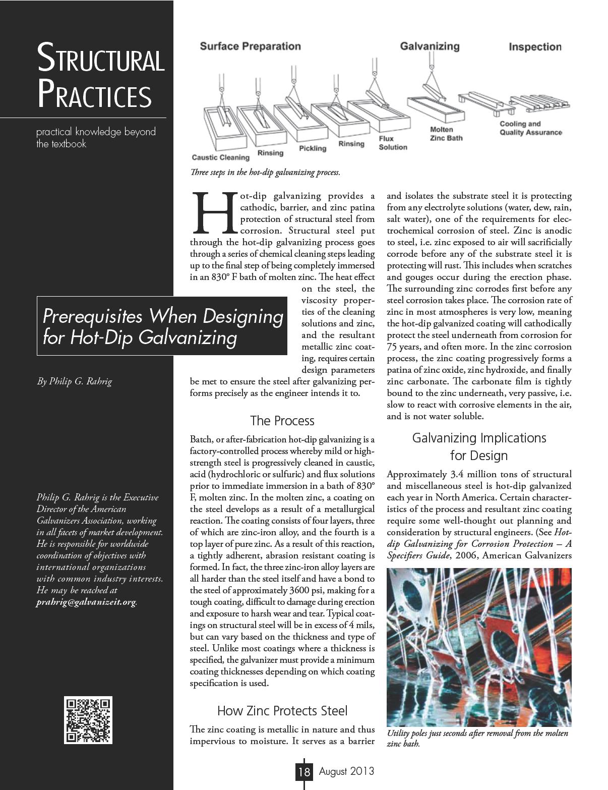
Association or Design Guide – The Design of Products to be Hot-Dip Galvanized after Fabrication , 2012, American Galvanizers Association, for more information)
Viscosity
Steel designs must provide venting and drainage outlets on the parts to be hot-dip galvanized. In the cleaning process of steel to be hot-dip galvanized, the fluids can penetrate between overlapped steel surfaces unless they are seal-welded. Because the viscosity of molten zinc is low compared to the cleaning solutions, it does not penetrate into the overlap areas. The temperature of the molten zinc is 830° F and creates a virtual high pressure enclosure in the overlapped areas, one which can explode, destroy the fabrication, and cause serious injury to the galvanizing personnel in the plant.
Vent/Drain Holes
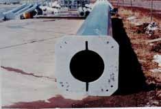
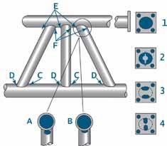
When immersing welded round, square, and rectangular hollow structural sections (HSS) with closed ends in molten zinc, there must be holes somewhere near both ends to allow air to escape out the top and molten zinc to
enter in the bottom. Otherwise, the air pressure doesn’t allow the zinc to flow throughout the inside of the piece, and consequently no zinc coating forms on the inside where most corrosion begins.
Welds
All welded areas must be clean and free of slag prior to arriving at the galvanizer’s plant. The cleaning solutions do not remove the slag and the result is uncoated steel.
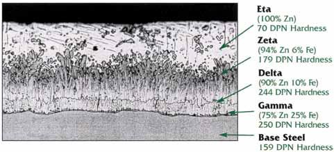
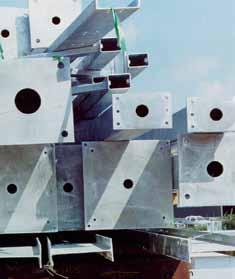
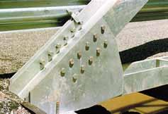
Coating Thickness and Bolted Connections
Tapped through-holes must be re-tapped oversize after galvanizing when used in conjunction with galvanized bolts, because the bolt shaft is slightly larger in diameter due to the addition of zinc coating to the bolt threads. Oversizing holes according to American Institute of Steel Construction (AISC) guidelines is usually sufficient to account for the zinc coating’s thickness.
Bolts are completely galvanized, but internal threads in holes or nuts must be tapped oversize after galvanizing to accommodate the increased diameter of the bolts. And, although the re-tapping or chasing cause a bare steel condition on the female thread, the zinc on the bolt threads protects both components from corrosion.
When galvanized bolts are used in conjunction with galvanized and faying structural members, the surface must be roughened or coated with a zinc-silicate paint to achieve a 0.5 coefficient of friction. Exact procedures for this roughening are currently being developed by the American Galvanizers Association. No special preparation of galvanized surfaces is required for bearing connections.
Mechanical Properties
According to studies by the BNF Metals Technology Centre in the UK (as well as numerous other national and international studies), hot-dip galvanizing produces no
significant changes in the mechanical properties of the structural steels or welds commonly used throughout the world. The galvanized substrate is chemically and metallurgically equivalent to the uncoated steel.
Embrittlement
Structural steel severely cold-worked (punched, notched, sheared, or bent sharply) is susceptible to strain-age embrittlement. This embrittlement is relatively slow to occur in ambient temperatures, but may be immediately evident after exposure to the elevated temperature of the galvanizing bath. Precautions such as selecting steel with carbon content less than 0.25%, bending with a radii of at least 3X the section thickness, and more are detailed in ASTM A143, Safeguarding Against Embrittlement of Hot-Dip Galvanized
Zinc is required for all organisms to live and reproduce. But, by far the largest use of zinc is to protect metal from corrosion via its application in the hot-dip galvanizing process.
Sustainability measurement is rapidly progressing to encompass the complete stream for any product from raw material to final use. For hot-dip galvanized steel this means measuring the energy consumed and emissions generated from the mining of zinc and steel, smelting, and application on steel to the recycling phase and back to raw material. The emphasis of the galvanizing industry is that no maintenance of galvanized steel is necessary for 70 years or more. This means the environmental impact is almost exclusively confined to the production phase. This is unlike most other coatings, which require periodic and frequent maintenance throughout their service life.
The only environmental impact during the use-phase results when the zinc coating corrodes over many decades and makes its way back into water and soil from which it was mined. When the zinc coating is exposed to air and goes through the natural wet and dry cycles of weather events (rain, snow, fog), it oxidizes and very slowly, often 75 years or more, makes its way into streams, rivers,
oceans, and lakes. These compounds (zinc oxide, zinc hydroxide, zinc carbonate) are added to the existing background level of zinc in the water, but only on a very temporary basis. The zinc level does not accumulate in water due to the interactions between zinc and the various water quality constituents present in natural waters. The suspended solids in water (minerals and coarse organic material) decrease the total zinc due to settling and are incorporated into the sediment. Over time, the system maintains a consistent ambient zinc concentration in the water column and sediment because there is a constant supply of new sources of suspended solids in the flowing water. These new sources remove and bury the zinc in a continuous cycle. Even if there are multiple sources of zinc, the dilution factor and suspended solids removal is such that the natural background level of zinc is relatively unchanged approximately 2500 feet downstream from each zinc source, and even closer for bodies of water with very large volumes such as oceans.
This addition of zinc to the water environment does not cause the background level of zinc to exceed the criterion level, defined by the U.S. Federal Clean Water Act, as the amount of zinc in water causing toxicity to aquatic organisms.
Summary
The hot-dip galvanizing process is unique in that it economically protects valuable structural steel from corrosion, but it requires some special design considerations in order to deliver the precise requirements specified by the structural engineer. When the structural engineer understands the governing specifications for hot-dip galvanizing and is in constructive communication with the architect, fabricator, and galvanizer, all expectations are met. And, the use of galvanized steel assures that sustainability has been integrated into the final project.▪


on a new and improved plan.” The bridge construction used 3,000 tons of oak timber, 2,000 tons of pine, 80,000 feet of 4-inch plank; 20 tons of iron; and 8,000 tons of stone. Enos Whiting of Norwich, Connecticut is credited with superintending the pile work, and also with constructing “a draw for the passage of shipping, which moves across in a horizontal direction, instead of being raised on hinges, but it is feared this expected improvement will not answer the purpose.”
Adams wrote “hundreds of people came long distances to cross and view the great enterprise that so auspiciously opened a new era in business. The Architect was Timothy Palmer of Newburyport, and the success of his work earned for him a great reputation. The entire bridge, [including the trestle spans and draw spans] cost $65,974.34, a large sum for those days.”
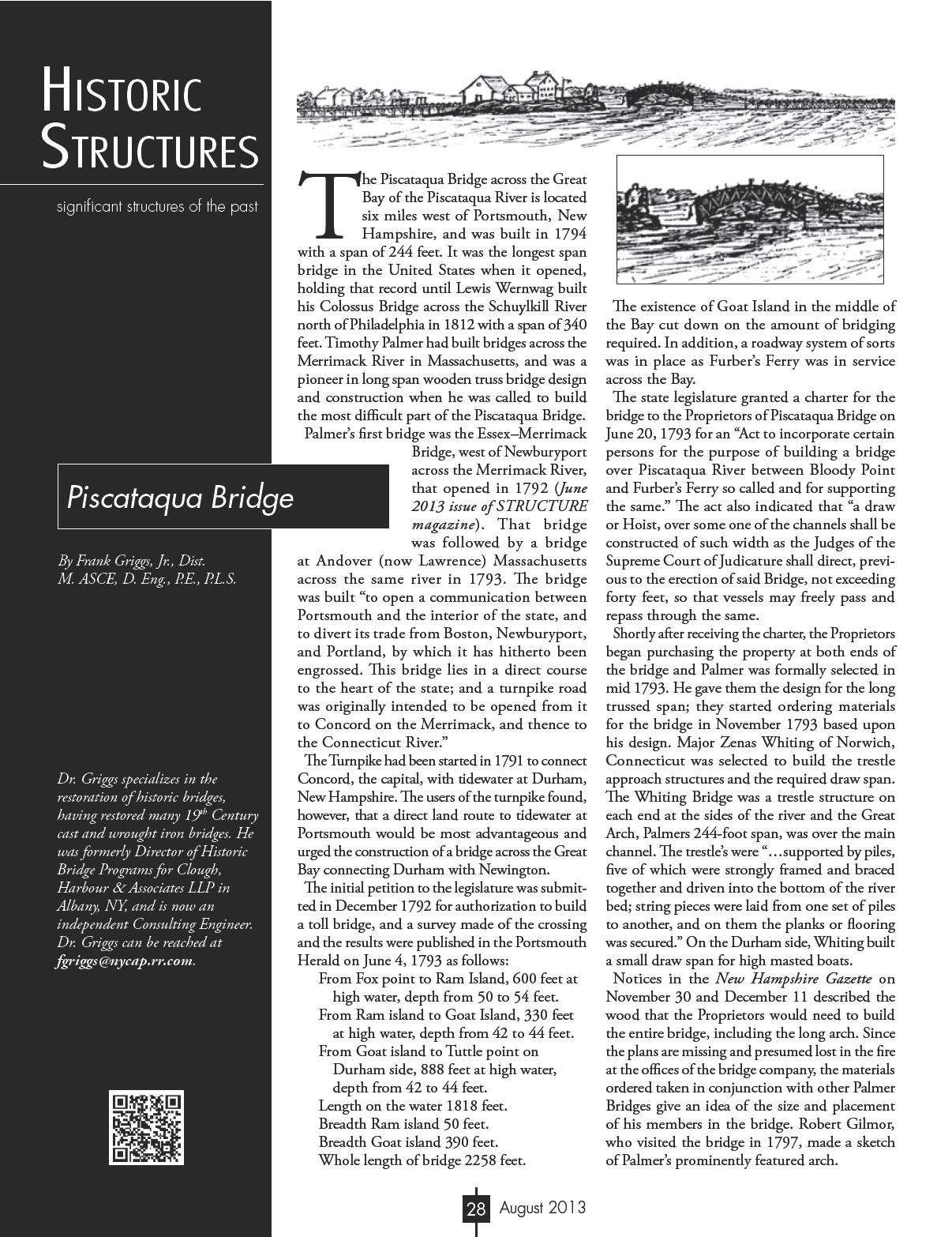
It is clear that Palmer’s top chord on this bridge was only at railing height, and that the deck was close to the top chord and some distance (16 feet) above the bottom chord. This was the first time he changed his normal method of bracing the top chords overhead. He determined that a deeper truss was required for the longer span and that it became more difficult to have overhead cross braces, even if connected with ships knees, to provide sufficient lateral bracing. By having the deck near the top chord, it is possible to cross brace the trusses below the deck down to the lower chord.
The bridge sparked a great deal of interest in the few international journals and books dealing with engineering subjects in the late 18th and early 19th century. The first written description of the bridge was in the Dictionary of Arts, Sciences and Miscellaneous Literature in its Supplement printed in Philadelphia in 1803: …a wooden bridge erected in North America, in which this simple notion of Grubenhamm’s is mightily improved. The span of the arch was said to exceed 250 feet, and its rise exceedingly small. The description we got is very general, but sufficient, we think, to make it perfectly intelligible. In… are supposed to be three beams of the arch. They consist of logs of timber of small lengths, supposed of 10 or 12 feet, such as can be found of a curvature suited to its place in the arch without trimming it across the grain. Each beam is double, consisting of two logs applied to each other side to side, and breaking joint, as the workmen term it. They are kept together by wedges and keys driven through them at short intervals…
Thomas Pope, in his 1811 A Treatise on Bridge Architecture, wrote that the “part which engages the attention of travelers is an arc nearly in the centre of the river, uniting two islands, over water forty-six feet deep. This stupendous arc of two hundred and fortyfour feet on the chord, is allowed to be a masterly piece of architecture, planned and built by the ingenious Mr. Timothy Palmer of Newburyport…”
Since the original plans for the bridge have been lost in a fire at the company offices in Portsmouth, it is necessary to rely on the observations of travelers, and later writers, who were not engineers or builders but who had actually seen the bridge and crossed it, to understand the design and construction of the bridge and the impact it had on users. Timothy Dwight crossed the bridge in the fall of 1795, and described it as follows: …This structure stands in a region which gives it every advantage to make a striking impression on the mind…we came suddenly upon the bridge, an enormous structure, twenty-six hundred feet in length, of an interesting figure, finished with great beauty and elegance, new, white, and brilliant. There are at this place two islands in the river; one, next to the southern shore, an oblong narrow rock: the other of sufficient extent for the site of house, garden, and some other enclosure…The whole scene had the appearance of enchantment, and in Arabia might not unnaturally have been attributed to the hand of a genie...Piscataqua bridge is formed of three sections; two of them horizontally, the third arched…The arch like the Haverhill Bridge [built in the following year] is triple, but no part of the work is overhead. The chord is 244 feet; and the versed sine, nine feet and ten inches. This arch is the largest in the United States, contains more than seventy tons of timber, and was framed with such exactness that not a single stick was taken out after it had been once put in its place. The whole length of planking is 2,244 feet. The abutments make up the remaining 356 feet and the island already mentioned…This is by far the most interesting structure of the kind which I have ever seen. Like the face in a well-contrived portrait, it is surrounded by such objects as leave the eye to rest on the principal one, and the mind to see but a single impression. Fletcher and Snow described the bridge as follows:
Its length was 244 feet, the rise was 27 feet 4 inches and the depth of framework of the arch, 18 feet 3 inches. There were three concentric ribs the middle one
carrying the floor of the bridge. The ribs were made from crooked timbers, so that the fibers were nearly in the direction of the curves, and they were connected by pieces of hard and incompressible wood, with wedges, driven between. The ribs were mortised to receive these connecting pieces and wedges, thus keeping an equal and parallel distance between them. Each rib was formed of two pieces, about 15 feet long, laid side by side in such a manner as to break joints. Their ends all abutted with square joints against each other, and were neither scarfed nor mortised. The two pieces of timber being held together by transverse keys and joints. All the timbers were admirably jointed and freely exposed to the action of the air. Any piece might be removed for replacement without injury to the remainder of the structure.
It, primarily the deck portion, was rebuilt in 1803 when a lottery was held to cover the reconstruction. It was unusual that a wooden bridge would have to be rebuilt in only 7 years, but exisiting uncovered in a New Hampshire coastal environment could have accounted for significant decay of some of its members. The tolls were not sufficient to cover expenses, and the bridge was never a financial success.
In 1818, Cyrus Frink, who had completed most of the earlier repairs, replaced the arch with “an entire new bridge, according to a wooden plan by him exhibited to the directors.” The reconstruction, including the new arch, was to be completed between June 4th and September 15th without obstructing or impeding the passengers. What his plan was, and how he replaced the main span while not cutting off traffic, is not clear. Whatever he did, it resulted in the removal of Palmer’s span.
Frink’s bridge gave way on March 18, 1830 and, after being rebuilt, gave way again in 1854 and was not repaired. An ice jam on February 18, 1855 took the remainder of the bridge out. By that time, traffic had decreased significantly due to competition from the railroad that had opened between Boston and Portland, Maine, and the bridge was not rebuilt.
This bridge was the most written about of any bridge in the country until Palmer’s Schuylkill River Permanent Bridge in 1805. Its 244-foot span was 84 feet longer in span than the Newburyport Bridge and incorporated an entirely unique framing plan, one that he, in part, was to use in his later bridges across the Schuylkill and Delaware Rivers.▪

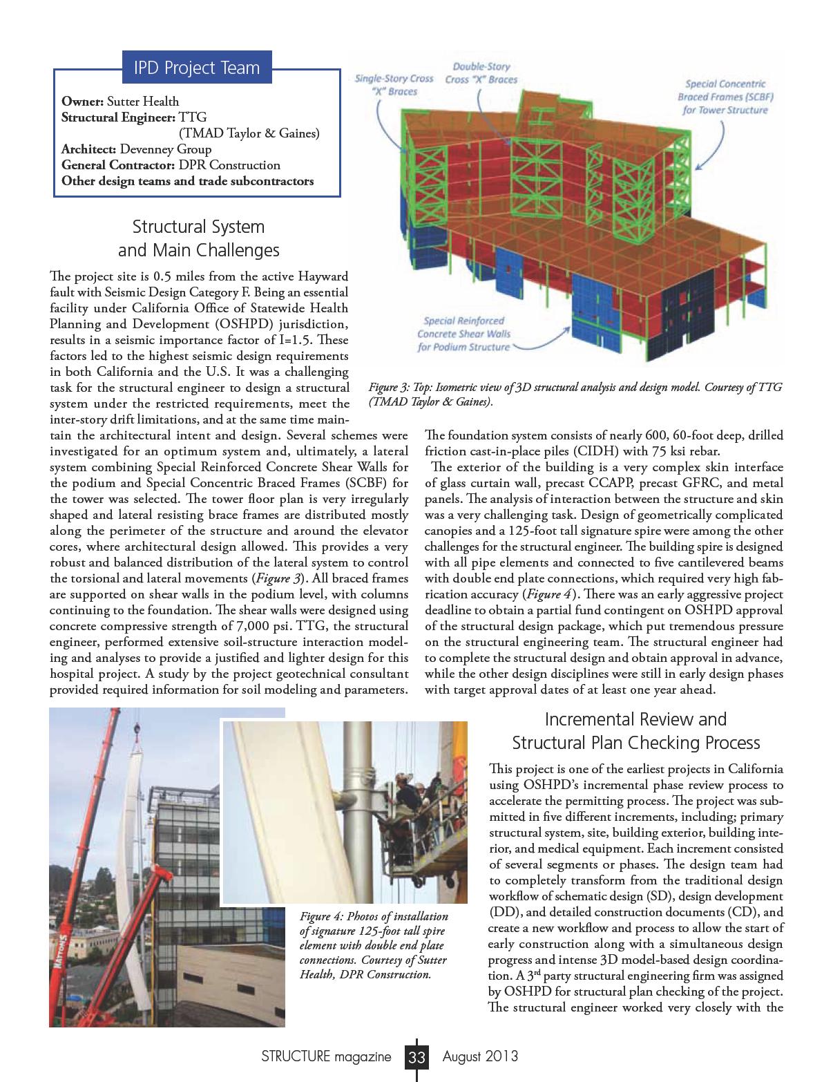
plan checking team through a detailed and delicate process, in which the review comments and responses were communicated in a weekly manner until all the comments were resolved and approval for the structural package was obtained on time.
3D Review of Structural Shop Drawings
This project is one of the 1st projects where the structural engineer reviewed shop drawings in full 3D format. The 3D review of structural steel shop drawings was conducted through direct exchange of TEKLA models between the structural engineer and the steel contractor in 22 different segments. The structural engineer worked with Herrick, the steel fabricator, to customize TEKLA for a more streamlined review process. At any point in time, the structural engineer was working on the review of new segments while back checking prior segments, sequentially. In addition, rebar installation shop drawings were also generated in 3D TEKLA models and reviewed in 8 different concrete pours. This allowed for a detailed constructability review by the structural engineer, general contractor, and rebar detailer. The 3D review process eliminated traditional methods of providing and mailing thousands of hard prints, resulting in savings in both project cost and in time.
In Conclusion
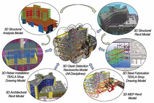
BIM-Based Design and Clash Detection
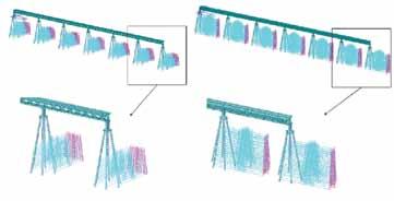
Extensive virtual design and building modeling efforts were utilized. Various 3D design models, along with 3D shop drawings models, were reviewed and clashed using Navisworks in a multi-disciplinary fashion (Figure 5 ). This process allowed the structural engineer and contractors to better understand the contact between the various structural and non-structural elements, and permitted resolving issues and conflicts ahead of time (Figure 6 ). Typically, these types of issues would not be identified and resolved until progress of construction, resulting in costly field repairs and delays.
SHEMC was the 1st full IPD, 11-Party IFOA project in the US and also one of the earliest OSHPD incrementally reviewed projects. The project was very successful. TTG, the structural engineer, played a significant role, utilizing advanced and innovative technologies to overcome challenges and contribute to the success of the project:
• All of the IPD goals were met or exceeded.
• Project delivered ahead of schedule, even with 30% fast track schedule.
• Project delivered on-budget, even with aggressive budget targets.
• The structural engineer produced fully coordinated and constructible drawings and 3D models.
• Steel delivered 6 months ahead of schedule with over $1 million in savings, returned to owner by steel contractor due to active collaboration between the structural engineer and steel contractor and IPD team in review of 3D shop drawing.
• Construction change orders & RFIs for structure were under 15% of estimates for comparable hospital projects in California.
• The project has won numerous design and construction awards.
• The project has been twice on cover page of Engineering News-Record (ENR) (September 2011 and May 2009 issues).▪

Mohammad Aliaari, Ph.D, S.E., is a Senior Associate, Structural Project Manager at TTG Office in Pasadena, CA. He can be reached at maliaari@ttgcorp.com
Edwin Najarian, S.E., P.E., is a Principal, Structural Vice President at TTG Office in Pasadena, CA. He can be reached at enajarian@ttgcorp.com