Publication of any article, image, or advertisement in STRUCTURE® magazine does not constitute endorsement by NCSEA, CASE, SEI, the Publisher, or the Editorial Board. Authors, contributors, and advertisers retain sole responsibility for the content of their submissions. STRUCTURE magazine is not a peer-reviewed publication. Readers are encouraged to do their due diligence through personal research on topics.
Structural steel, exposed concrete, and mass timber converge to realize the Museum’s interlocking pavilion design.
By Jason Tipold, PE, SE
24
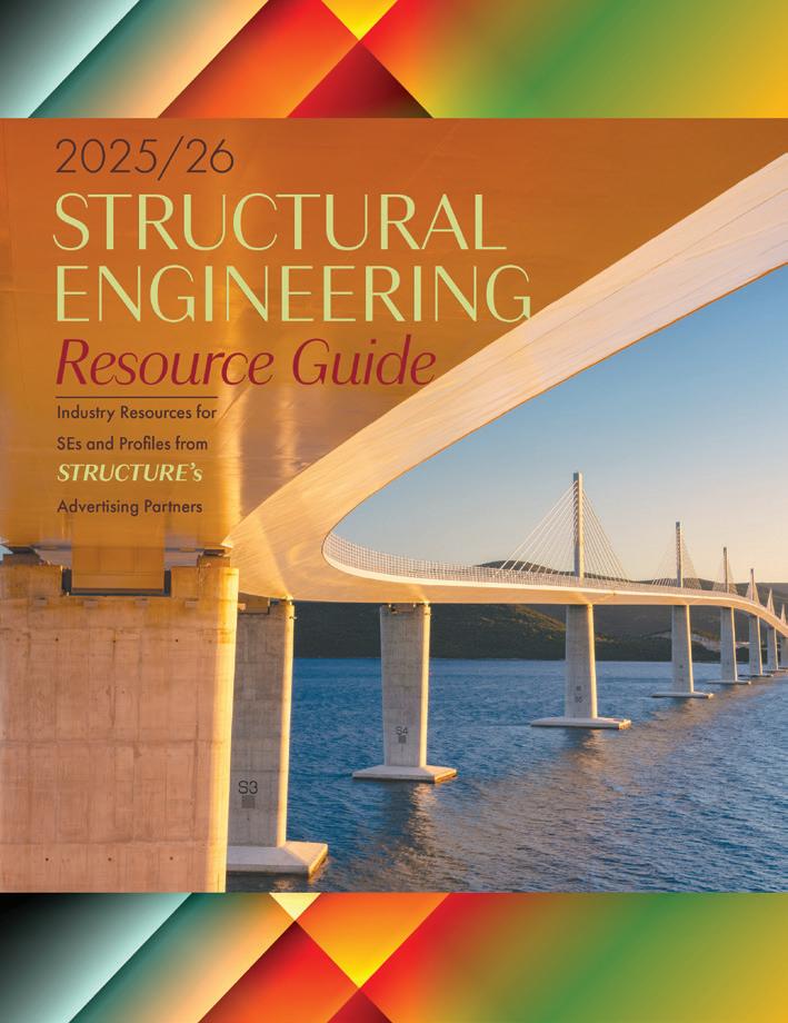
BRIDGING NATURE & STRUCTURE: CREATING A GATEWAY TO BENTONVILLE’S TRAIL SYSTEM
By Aaron Kilgore,
PE, Austin Curnutt, SE, PE, and Bryce Crady, PE
A harmony of structure and landscape defines Bentonville’s 8th Street Gateway
COLUMNS and DEPARTMENTS
Chad S. Mitchell, SE,
Pawan Bhattarai,
Hardik Shah
Devin Bowman
Jeannette Torrents,
Ralph Hage
John Dal Pino
EDITORIAL
It Is OK to Make Changes
By Chad S. Mitchell, PE, SE
Two years ago, I wrote an article for STRUCTURE called “It Is OK to Struggle,” (May 2024) where I opened up about burnout, stress, and the silent pres sure many of us in structural engineering feel to constantly perform. The response I received, messages from peers, early‑career engineers, and even senior leaders, made me realize how many people had been shoulder ing similar weight in silence. Since then, my life and mindset have changed in meaningful ways, and I felt compelled to continue the conversation.
My local structural engineering community has been invaluable in helping continue this conversation. Our local NCSEA SE3 com mittee has participated in several mental health presentations and panel discussions, both locally and nationally, often alongside mental health professionals (because, hon estly, I’m no expert). Through this work, we even developed a workshop for our structural engineering association aimed at opening discussions with firm leaders and HR pro fessionals about how to build and sustain a mentally healthy workplace.
One of the most significant changes for me was finally committing to therapy. For years, I convinced myself I could manage stress on my own. Therapy helped me realize that resil ience isn’t about pushing through, it’s about understanding myself more deeply, including my neurodiversity. It taught me to recognize the early signs of overwhelm and gave me tools to navigate them. Most importantly, it gave me permission to speak up when I’m struggling instead of just gritting my teeth and powering forward. Those conversations have allowed me to show up more honestly and more effectively.
It’s still a continuous journey, and I’m far from finished. Even though I’ve talked about mental health with hundreds of structural engineers, I still find it difficult to open up about my own mental health with the people I love and to let them know I’m here to support them through theirs.
Another major turning point was leaving a job after nine months. Engineers are wired to
finish what we start, so admitting something isn’t the right fit is difficult. Finding myself in a role that was an amazing opportunity but didn’t align with my strengths or abilities only amplified my stress. Walking away felt like failure at first, but it was growth. Recognizing misalignment early, and acting on it, is far healthier than forcing yourself into a role that does not work for either party and only dims your passion for the profession.
“We
must encourage engineers to speak up when they’re over whelmed, to explore career paths, within our profession, that align with their strengths, and to recognize when change is necessary for their well‑being. ”
While my personal journey has evolved, so has the landscape of structural engineering. Our industry is facing compounding pres sures: shrinking workforce capacity, increasing retirements, and higher project demands. Younger engineers want to contribute mean ingfully but often find themselves overloaded with production work and little mentorship. Senior engineers want to train the next gen eration but are pulled in too many directions to do it effectively. Retention suffers, work loads grow, and the cycle repeats. We can’t keep operating like this.
One emerging tool that gives me hope is artificial intelligence. Not as a replacement for engineers, but as a partner that can free us from the mundane tasks that steal our time and energy. AI can help draft let ters, summarize code provisions, assist with checking calculations, organize training mate rials, and yes—even help outline or refine a STRUCTURE Magazine article. These are small tasks individually, but together they consume hours per week that could instead be spent mentoring younger engineers, diving
deeper into complex design challenges, or simply maintaining a healthier workload.
For early‑career engineers, AI can serve as a supplemental teacher. Though never a substitute for human guidance (AI does have a long way to go), it can be developed into a tool that helps new engineers understand concepts through quick examples, alterna tive explanations, or visualizations. Imagine a new engineer experimenting with lateral load paths or connection detailing and instantly generating conceptual sketches or code references for comparison. That kind of support accelerates learning without burdening senior staff.
But to unlock that potential, we must be intentional. Firms need to create cultures where asking for help is normal, where workloads are realistic, and where people— not just projects—are prioritized. We must encourage engineers to speak up when they’re overwhelmed, to explore career paths within our profession that align with their strengths, and to recognize when change is necessary for their well‑being. At the same time, we must embrace tools like AI not as threats but as opportunities to reclaim time for high‑value work and human connection.
My hope is that by sharing these experiences, therapy, change, vulnerability, and optimism for the tools ahead, we can continue shap ing a healthier, more sustainable profession. Structural engineering will always require precision, creativity, and responsibility, but it should not require sacrificing our mental health or losing ourselves in the process. If we commit to supporting one another, investing in development, and using technology wisely (keeping the humanity in our profession), we can leave this industry better than we found it, for the next generation and for ourselves. ■
Chad S. Mitchell is senior structural engineer at SmithGroup. He also serves on the NCSEA Board of Directors.
structural DESIGN
quick experimental studies.
By Pawan Bhattarai, M.S.C.E, EIT
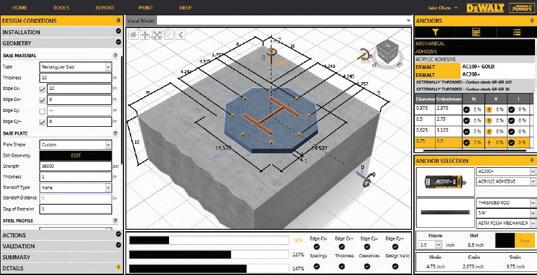
Modern structural engineering is advancing as quickly as the technology that supports it. What once began with hand drawn sketches and manual calculations has now evolved into a digital era where intelligent modeling, simulation, and data driven workflows define every stage of design. Powerful tools such as finite element analysis (FEA) have been a foundation of structural engineering practice for decades, with modern programs demonstrating the longstanding use of code and text-based modeling. As these tools grew more capable and complex, graphical user interfaces (GUIs) became the primary way engineers built models and reviewed results. Today, the increasing use of application programming interfaces (APIs) allows engineers to interact with these same models in ways that are often more efficient and flexible than other workflows. As projects become larger and more intricate, many professionals are realizing that true efficiency doesn’t always come from more complex software, it often comes from simpler, smarter customization. This customization often shows up as small, focused programs that automate calculations, check results, or extract and process data, allowing engineers to tailor their workflows without overhauling their primary analysis tools, and it is called scripting. In practice, scripting appears in two common forms. Standalone scripting, often written in languages such as Python or MATLAB, is used to perform calculations or verification checks outside of commercial software. API based scripting, typically implemented using Python, C#, or VBA, allows engineers to programmatically control or query commercial FEA tools. In both cases, scripting complements traditional analysis software rather than replacing it, enabling engineers to automate repetitive tasks, verify results, and run targeted studies that deepen understanding and improve design confidence.
The Rise of Intelligent Tools
Recent advancements in structural engineering software have changed how engineers interact with analytical models, largely by making commercial tools more open to automation and external control. Rather than relying solely on graphical user interfaces GUIs, many widely used programs now allow engineers to interact with models programmatically through scripting tools and APIs. Commercial engineering software falls into three main categories when it comes to automation:
• Some analysis software relies primarily on text-based input files and produces results in text-based output tables. Tools such as GT STRUDL and Open Sees follow this approach, which has been used in bridge and research-oriented applications. While these programs don’t provide built-in scripting environments or live APIs, their transparent file-based structure allows engineers to leverage external scripting tools to generate input files, automate parametric studies, and post process results.
• Many commercial platforms include built in scripting environments or automation environments, allowing users to write small programs directly within the software. These tools commonly based on languages such as Python, C#, or VBA and can be used to automate tasks like generating geometry, creating load combinations, running analyses, or extracting results. In parallel, low code and graphical scripting tools, such as Dynamo in Revit or Grasshopper for parametric modeling, provide an accessible entry point for engineers who want to automate workflows without extensive programming experience.
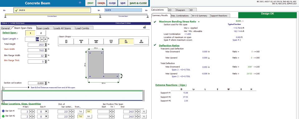
A Cantilever Beam Script in Python
To illustrate how scripting can complement structural analysis, consider an engineer who is reviewing internal forces and reactions from a commercial FEA model of a cantilevered structural element subjected to combined loading. The desired goal is to confirm whether the shear forces, bending moments, and sign conventions are reasonable or not before relying on the full model for design decisions. In that case, the engineer can use a low code external script made up of Python that calculates shear forces and bending moments in a cantilever beam. While the full version uses a class-based structure for clarity and reusability, beginners can start with a straightforward procedural version to perform the same calculations. The example works in U.S. customary units. Scan the QR code for the full code.
The provided script models a 15-foot cantilever beam subjected to a 12 kip point load at 6 feet from the support and a uniform load of 3 kip/ft from length 2 feet to 7 feet. It calculates and displays the shear force and bending moment at several points along the beam, as well as the fixed end reactions at the support. The output provides a clear snapshot of how the beam responds to combined loading, helping verify that the distribution of forces and moments aligns with theoretical expectations.
Fixed-end reactions:
Shear V(0) = -27.000 kips
Moment M(0) = -139.500 kip-ft
• Different software exposes open APIs, which allow external scripts to interact with analysis models from outside the primary application. An API enables engineers to programmatically create and modify models, assign loads and boundary conditions, execute analyses, and extract results using a general purpose programming language. In many cases, this interaction can occur without manual input through the GUI, effectively turning commercial FEA software into a programmable analysis engine rather than a static design tool. Together, these capabilities shift engineers away from manual data entry and repetitive clicking toward more efficient, logic-driven workflows. By defining how a model is built, analyzed, and checked through scripts, engineers can automate verification, perform parametric studies, and maintain clearer control over assumptions while continuing to rely on trusted commercial analysis software for core computation.
Choosing the Right Scripting Language
Engineers now have several effective options for scripting, each with clear strengths:
• Python has become the most popular choice for new automation work. Its clean syntax, rich ecosystem (including pandas, numpy, scipy, etc.), and broad community support make it excellent for batch processing, parametric studies, result postprocessing, and connecting multiple programs.
• VBA excels at quick, low effort tasks. It requires no extra
installation and integrates seamlessly with Excel, making it ideal for one-off checks, load combination tables, and spreadsheet-driven reporting.
• C# is preferred when performance, strong typing, or custom plugins are needed such as building Revit add-ins or highspeed tools that interact with ETABS.
Most engineers start with Python for broader workflows and keep VBA for fast Excel-based tasks.
Finite Element Analysis in Context
FEA is a mature and indispensable tool in structural engineering, but the quality of its results remains closely tied to the assumptions made during model development. Boundary conditions, mesh refinement, material properties, and load definitions all have a significant influence on predicted behavior, and small modeling choices can lead to meaningful differences in results.
Since these assumptions are often difficult to evaluate through a single model run, engineers frequently rely on judgment and experience to assess whether results are reasonable. This is where scripting becomes a valuable companion to FEA. By automating model variations such as adjusting boundary conditions, refining mesh density, or modifying load cases, engineers can efficiently perform parametric studies that reveal how sensitive a model is to key assumptions. Rather than replacing engineering judgment, scripting helps expose trends, confirm expectations, and build greater confidence in analytical results.
Scripted Truss Analysis Using GT STRUDL—A Bridge Example
Scripting allows engineers to perform quick checks and automate repetitive tasks, even for truss or bridge structures. Historically, command-based tools like GT STRUDL demonstrated that structural analysis could be performed entirely without a graphical interface. Today, modern scripting environments and APIs extend the same principle, enabling engineers to control bridge models, assign loads, and extract results programmatically.
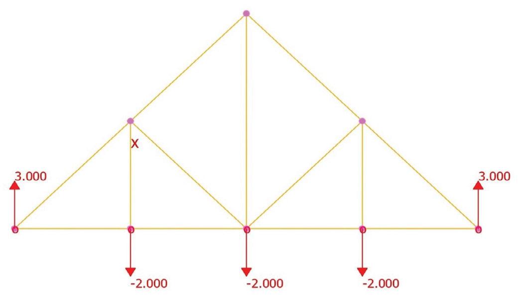
Consider a 20 foot long, 10-foot-high Howe truss, representing a small bridge span. The truss is defined by joint coordinates and member connectivity, with pinned and roller supports representing typical boundary conditions. Vertical loads are applied at interior bottom chord joints. Using a headless/scripted workflow, the stiffness-based solver computes member forces without manual GUI interaction.
Practical Connection to Bridge Design:
• Truss analysis can approximate the flow of internal forces in a beam, particularly for regions with discontinuities or heavy point loads.
• Engineers can use the calculated axial forces in truss members to inform strut-andtie models (STM) of the same structural element. For example, a deep beam or bent cap can be modeled as a combination of compression struts and tension ties.
• By analyzing truss representation of a beam, designers can identify critical struts and ties, determine their force magnitudes, and optimize reinforcement placement.
• This approach allows rapid iteration: once member forces are known from the truss model, they can directly guide reinforcement layout, tie sizing, and bent cap detailing, improving efficiency and confidence in the design.
Key Takeaways from Scripted Truss Analysis:
• Explicit assumptions: Units, geometry, supports, and loads are clearly defined, leaving little ambiguity.
• Shared theory: The stiffness method is the same fundamental approach behind today’s finite element software.
• Structural thinking first: Command based or scripted modeling encourages engineers to focus on load paths and force flow rather than navigating GUI menus.
• Design application: Forces from the truss analysis can feed STM for bent caps, deep beams, or other discontinuity regions, linking analytical modeling to practical reinforcement design.
The resulting member forces in the below table confirm the expected axial force distribution for a Howe truss under vertical loading. Compression and tension patterns align with theoretical predictions, providing a clear verification of both modeling assumptions and solver behavior. When considered alongside the python cantilever example, this truss model reinforces a central message of this article, i.e. scripting whether through modern code or command window connects theory, verification, and full-scale analysis. It strengthens structural intuition and builds confidence in computational results by making the engineer’s assumptions and logic visible.
Fig. A. Geometry and member layout along with loads and reactions of the 20-ft Howe truss obtained from GT STRUDL
Scripting as a Companion to FEA
Scripting has long been used to automate tasks in structural analysis, but modern integration through APIs has expanded its role, redefining how engineers interact with FEA models. Short, customized scripts often written in different programming language or through APIs allow engineers to automate tasks, perform quick verifications, and explore “what-if” scenarios within minutes. These small, focused programs can check reactions, moments, or deflections, providing independent validation before larger models are built.
Scripting brings flexibility, transparency, and control to the design process. Every assumption such as load magnitude, span length, boundary condition, or sign convention is clearly visible in the code, making reviews and revisions straightforward. Engineers can modify parameters instantly, test different configurations, and compare results efficiently. Beyond verification, scripting automates repetitive tasks such as load combinations, geometry generation, and data extraction, saving time for more creative and analytical work. It blurs the line between programming and engineering which helps in transforming models into intelligent, adaptive systems.
Looking Ahead
The future of structural engineering is moving toward a seamless blend of coding and design. Upcoming generations of engineers will likely spend as much time in scripting environments as in drafting
software, using custom code as the bridge that connects analysis, documentation, and data management. Writing a few lines of Python to analyze a beam or having a simple command code to analyze a truss might seem simple, but it represents a deeper shift of engineers gaining control over their tools rather than relying solely on commercial software updates. Through scripting, they can create solutions that are precise, transparent, and tailored to their needs. At its best, coding transforms computation into craftsmanship, empowering engineers to think critically, test ideas rapidly, and design with greater confidence and clarity. ■
Full references are included in the online version of the article at STRUCTUREmag.org .
Bhattarai, M.S.C.E., EIT, graduated with a degree in civil engineering from Idaho State University and works as a bridge engineer in the state of Arkansas. His professional interests include bridge design, structural analysis, and the application of computational methods in civil engineering practice.
Pawan
structural DESIGN
Value Engineering of Reinforced Concrete Cantilever Balcony Systems
Designing the balconies at Singh Tower in New Jersey as a reinforced concrete cantilever rather than steel-framed assemblies yielded cost savings and improved constructability.
By Hardik Shah SE
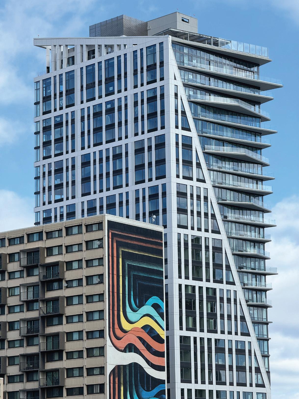
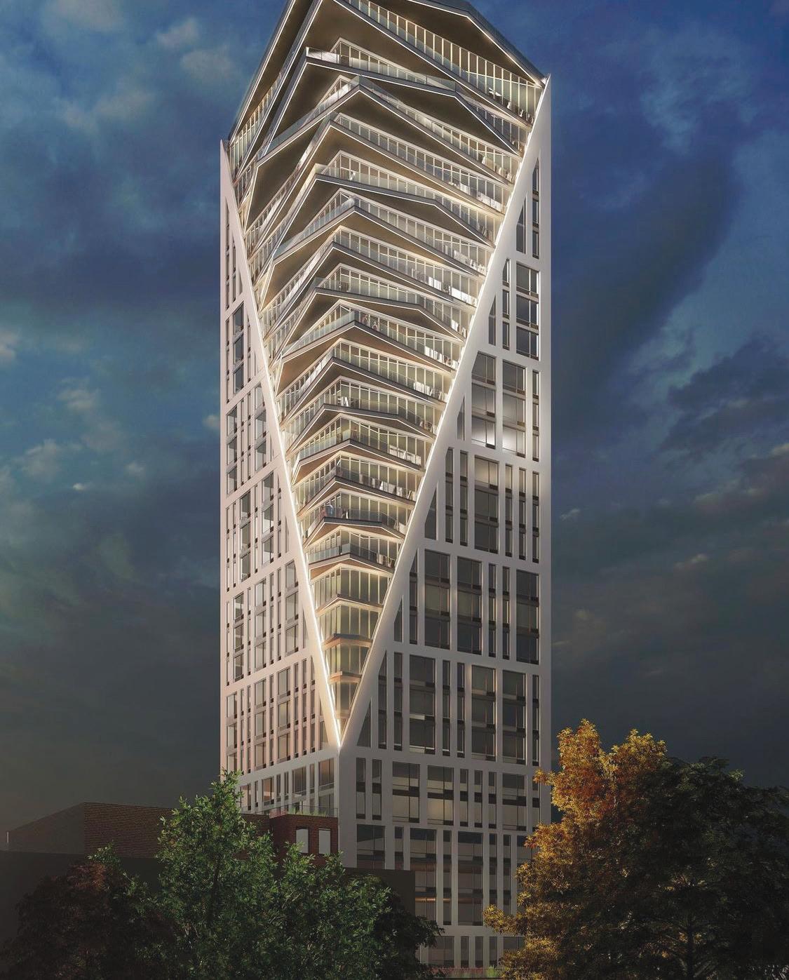
Singh Tower is a high-rise residential development located at 626 Summit Avenue in Jersey City, New Jersey. During the design development phase, the project team evaluated alternatives to the originally proposed steel-framed balcony assemblies. Through a structural value engineering study performed by OM Consulting Engineers Group LLC (OMC), the balcony system was redesigned as a reinforced concrete cantilever integrated into the primary slab system. The redesign improved constructability, reduced long-term maintenance risks, and generated measurable cost savings while maintaining compliance with governing building codes and structural performance requirements.
The Singh Tower development consists of a mixed-use residential high-rise with retail and amenity spaces on lower levels and residential units above. The building reaches approximately 285 feet in height and includes approximately 198,000 square feet of construction area.
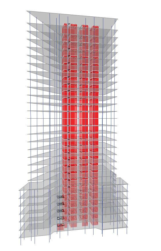
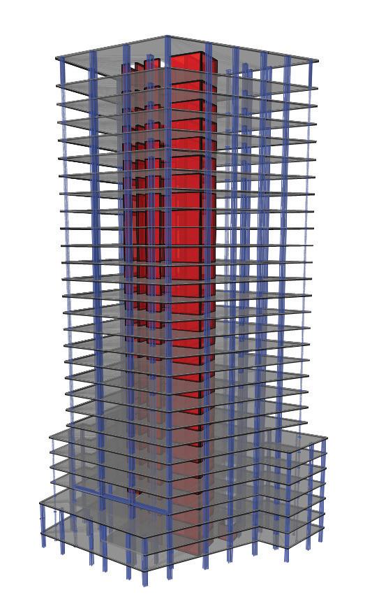
The structural system for the 29-story building consists primarily of reinforced concrete flat plate slabs supported by concrete columns and shear walls. Residential floors extend above podium levels and include cantilevered balcony projections from several floors.
Typical floor slabs are 9 inches thick, while the first floor slab is 10 inches thick and the main roof slab is 11 inches thick.
The structural system was analyzed using ETABS and SAFE finite element software. A 3D analytical model was developed to evaluate gravity, wind, and seismic loads.
Design Loads and Analysis
Design loads were determined in accordance with the 2018 International Building Code (New Jersey Edition). Typical residential floors were designed for 40 psf live load, while higher loads were applied to retail, gymnasium, and roof terrace areas.
The building was designed for a basic wind speed of 113 mph and analyzed using the equivalent lateral force procedure. Wind base shear values were calculated from ETABS analysis.
Lateral Force Resisting System
The lateral system consists of reinforced concrete shear walls located around the elevator and stair core. The system provides
resistance to wind and seismic forces. Drift analysis showed roof displacements of approximately 1.61 inches in the north–south direction and 2.98 inches in the east–west direction at the top of the structure.
Foundation System
The building foundation system consists primarily of spread footings bearing on rock with an allowable bearing capacity of approximately 20,000 psf. A mat foundation supports the stair and elevator core to distribute concentrated loads from the shear wall system.
The structural system was analyzed using ETABS and finite element analysis to evaluate gravity, wind, and seismic loads.
Singh Tower is 29 stories and reaches 285 feet in height. It features reinforced concrete cantilever balconies.
Balcony Structural Design Challenge
The original structural design utilized steel-framed balcony assemblies connected to the reinforced concrete floor system. While structurally viable, this configuration introduced complexity in steel-to-concrete connections, potential thermal bridging, and long-term corrosion concerns.
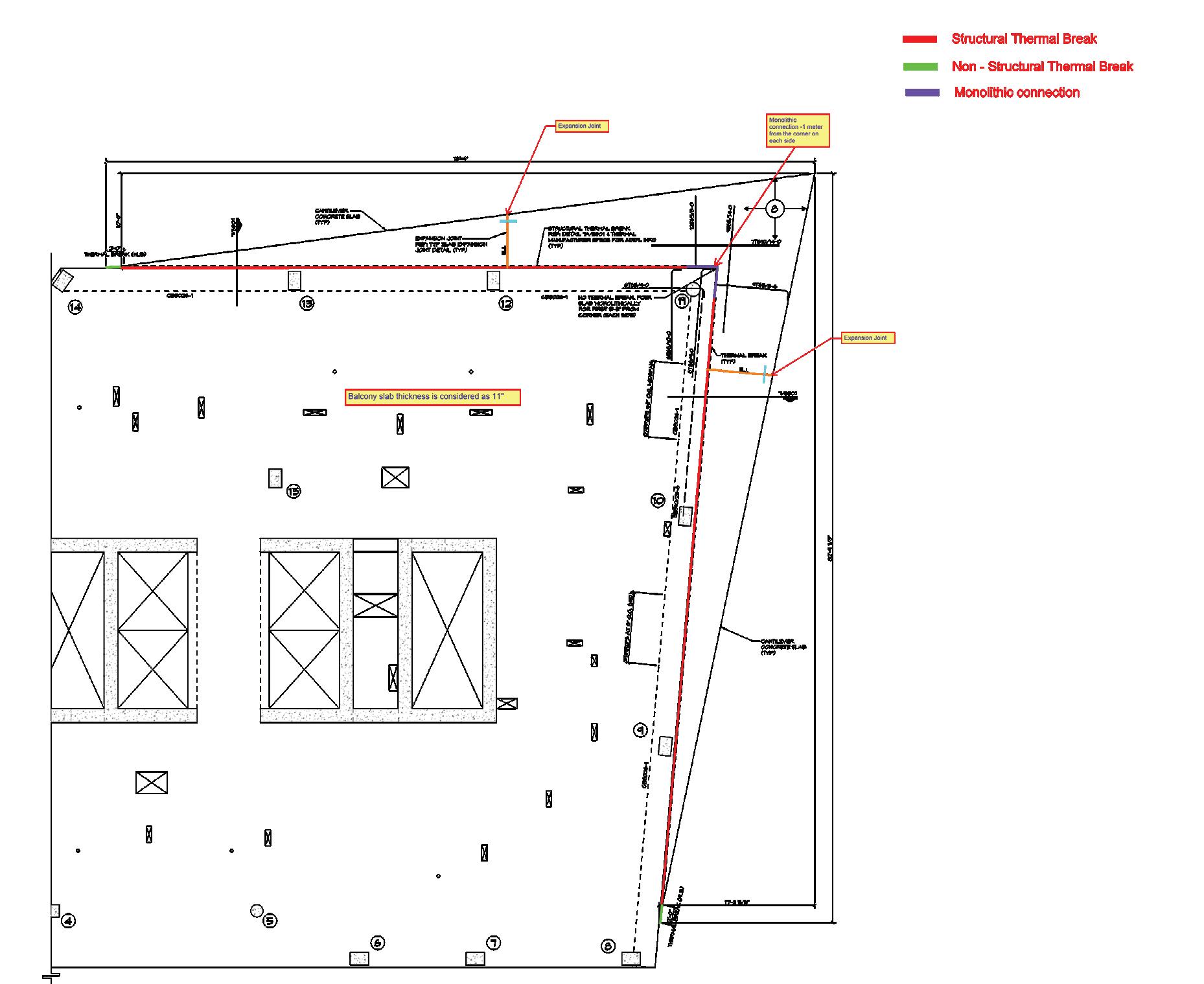
A structural value engineering study was performed to evaluate whether the balconies could be constructed using reinforced concrete integrated directly into the floor slab. The revised concept extended the floor slab outward to create cantilevered balcony slabs with additional reinforcement to resist negative bending moments at the support.
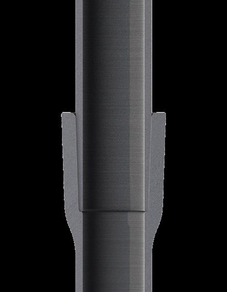
Shown is the detail for the 29th floor cantilever balcony. Red indicates the structural thermal break, green indicates nonstructural thermal break, and purple highlights the monolithic connection.
check out this video
THE LEADING CHOICE FOR CONCRETE STRENGTHENING
Boundary-pushing building systems that stand the test of time.
Construction Advantages
The concrete cantilever system simplified construction by elimi nating structural steel fabrication and erection. Balconies were cast monolithically with the floor slabs, reducing coordination between trades and allowing a consistent floor construction cycle.
The value engineering modifications resulted in a more efficient structural system while maintaining safety and performance. Structural optimization across multiple elements resulted in potential material savings of approximately 10–15 percent while improving long‑term durability.
Conclusion
The Singh Tower project demonstrates how structural value engineering can enhance constructability, durability, and economic efficiency. By integrating cantilever balconies into the reinforced concrete slab system, the project team achieved a simplified structural solution without compromising architectural intent or structural performance. ■
Hardik Shah is a Senior Project Structural Engineer at OM Consulting Engineers Group LLC in Jersey City, New Jersey. He specializes in high‑rise concrete structures, value engineering, and performance‑based structural design.
Singh Tower at 626 Summit Avenue in Jersey City, New Jersey, is a mixed-use residential high-rise.
Credibility Built on Performance
Concrete materials and specifications continue to evolve. Modern concrete systems - those that incorporate new cements, supplementary cementitious materials, specialty admixtures, etc. - are frequently utilized to address performance, economic and environmental considerations.
Premiere Concrete Admixtures works with architects, engineers, concrete producers, material suppliers and contractors to support informed decision-making in an ever-changing materials landscape. Our approach emphasizes documented performance and system compatibility.
Premiere admixtures are developed and tested based on measurable performance and documented behavior, not generalized assumptions. We recognize that cement chemistry varies not only between manufacturers but has been impacted by the introduction of 1L cement. As a result, admixture selection should complement the cement being utilized for optimum performance.
Premiere offers a full range of chemical admixtures for industrial, commercial, and DOT applications that meet applicable ASTM specifications. When performance challenges arise, admixtures can play a meaningful role in achieving specification intent.
If you have questions about the role admixtures play within your concrete systems, Premiere Concrete Admixtures is available as your technical resource.
Our Innovative Specialty Admixture Applications
Within modern concrete systems, specialty admixtures can be utilized for defined performance outcomes rather than generalized usage. Examples from Premiere Concrete Admixtures include:
Impede® IntraSeal
A hydrophobic, non-corrosive admixture developed for its ability to reduce water and deicing salt brine intrusion by modifying the internal pore structure of the concrete. IntraSeal is recommended for applications where freeze-thaw resistance, and surface durability, is an important consideration. It can be used year-round to protect exterior concrete from damage resulting from freeze-thaw cycles.
UltraFinish 1L
A colloidal silica admixture developed for use in concrete incorporating Type 1L cement, where changes in cement properties can influence field performance, particularly finishing characteristics and surface behavior. Applications include placements where moisture retention during finishing is critical and where mitigation of plastic shrinkage cracking associated with moisture loss is essential.
These admixtures are intended to be evaluated as part of the complete concrete system, with performance dependent on mixture design, placement, finishing, and curing practices.
Gordie Howe International Bridge
Photo courtesy of the Gordie Howe International Bridge Project
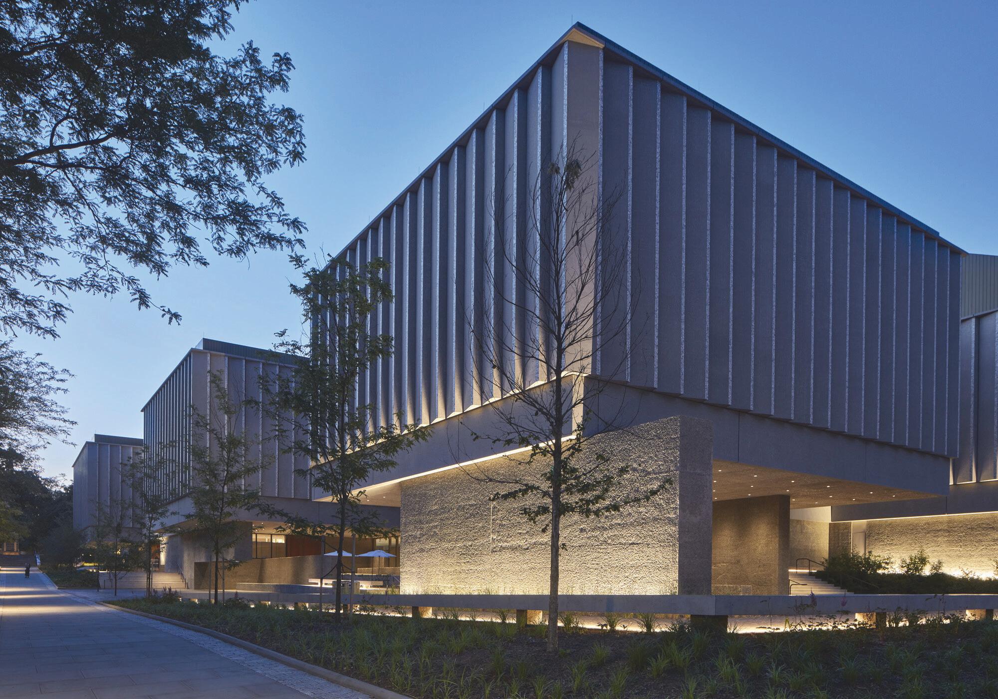
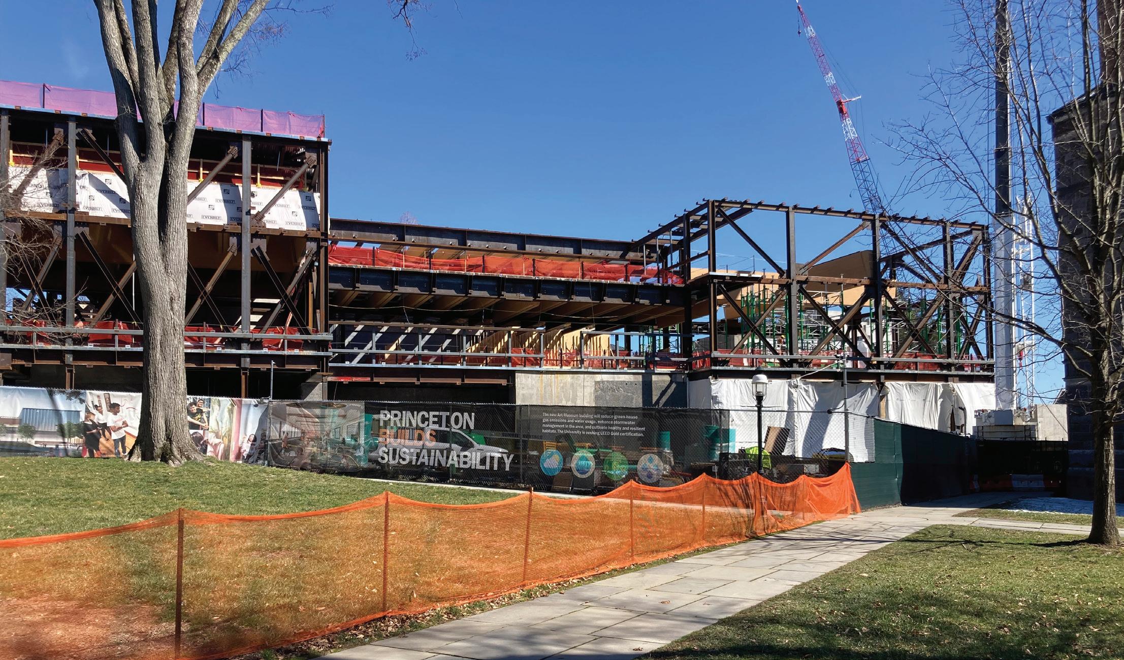
Princeton University's Art Museum
Structural steel, exposed concrete, and mass timber converge to realize the Museum’s interlocking pavilion design.
By Jason Tipold, PE, SE
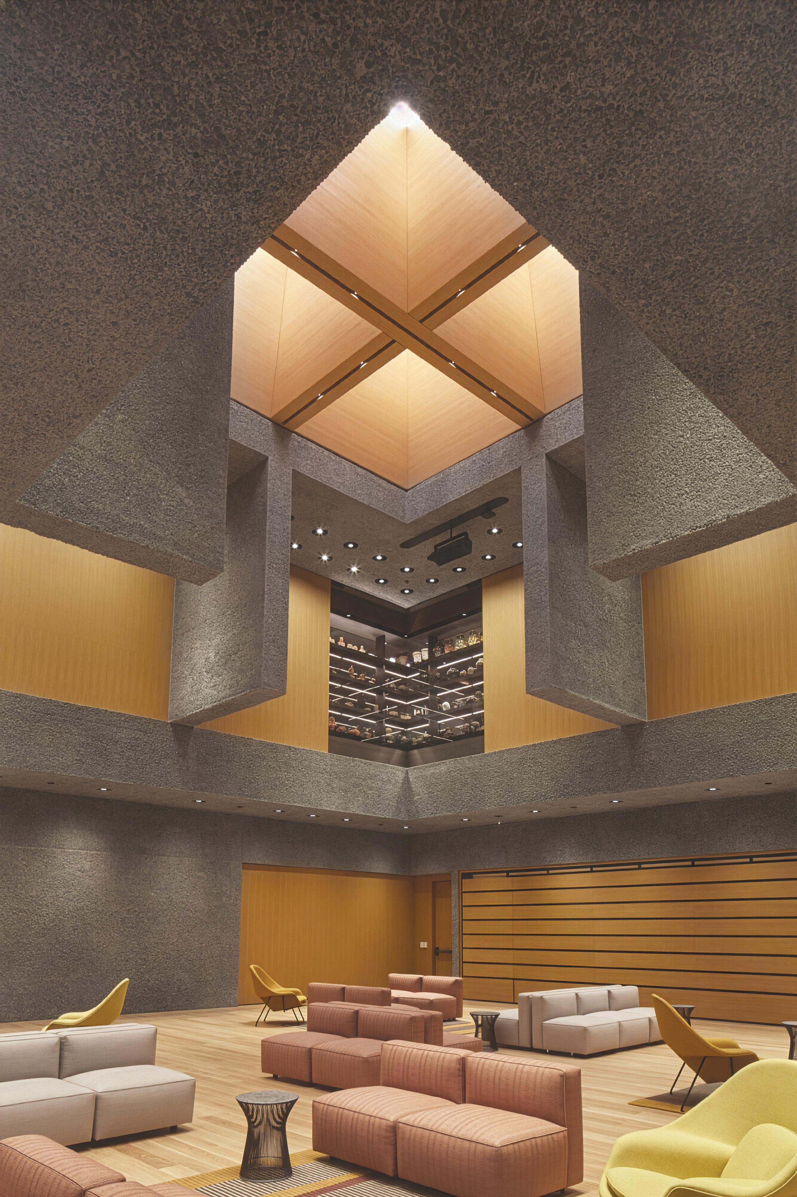
The west side pavilion galleries of Princeton University Art Museum as viewed from the southwest.
The new Princeton University Art Museum (PUAM) exemplifies the synthesis of architectural vision and structural innovation required to realize an ambitious and highly complex museum program. Designed by Adjaye Associates with Corgan (formerly Cooper Robertson) serving as executive architect, the 146,000-square-foot facility on the site of the former museum is organized as nine interlocking pavilions that nearly double the museum’s size while carefully integrating with the historic campus fabric. The project team included TY Lin (formerly Silman) as structural engineer, Kohler Ronan as MEP engineer, Heintges as facade consultant, and LF Driscoll as construction manager, with major
Design Team
Structural Engineer:
TY Lin (formerly Silman)
Architects:
Adjaye Associates (design) and Corgan (formerly Cooper Robertson, executive)
MEP Engineer: Kohler Ronan
Facade Consultant: Heintges
Construction Manager: LF Driscoll
Steel Subcontractor: Kinsley Steel
Concrete Subcontractor: Madison Concrete
Glulam Subcontractor: Nordic Structures
structural trade partners Kinsley Steel, Madison Concrete, and Nordic Structures.
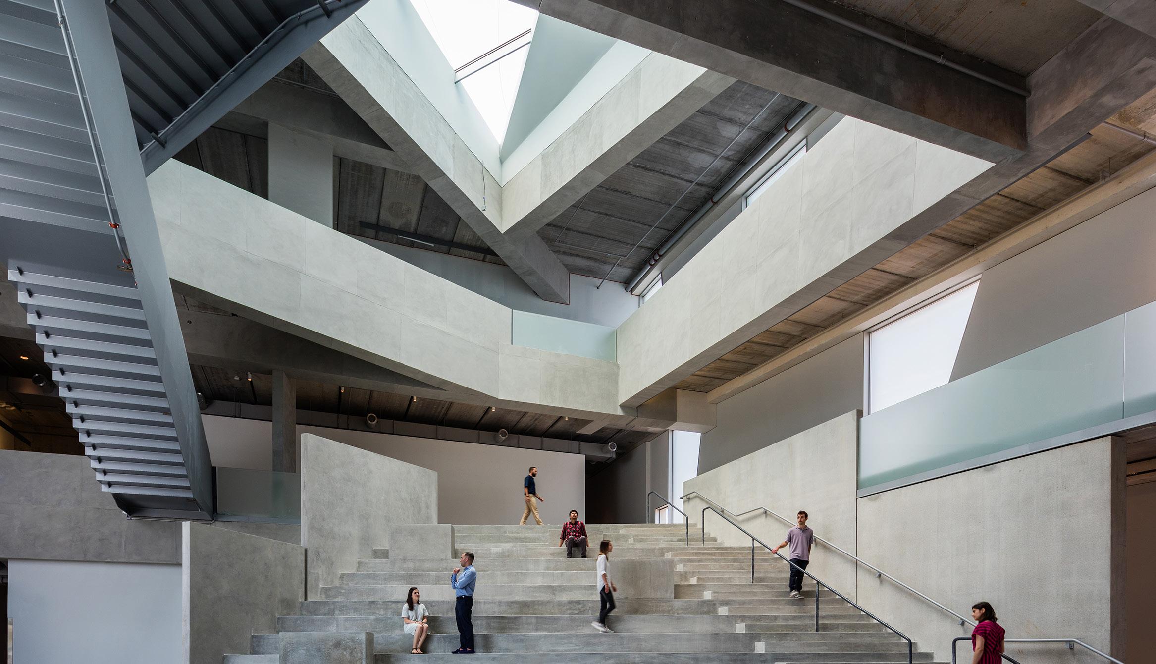
The architectural concept is supported by a sophisticated hybrid structural system composed of structural steel framing, architecturally exposed cast-in-place concrete, and massive glued laminated timber (glulam) elements. Together, these systems enable large column-free gallery spaces, long-span floor plates, and a dramatic three-story Grand Hall that serves as both a public gathering space and a central organizing element. Circulation and transparency are emphasized through dual interior “art walks” that intersect on level one of the museum and connect programs across multiple levels, as well as through multiple ground-level entrances that strengthen
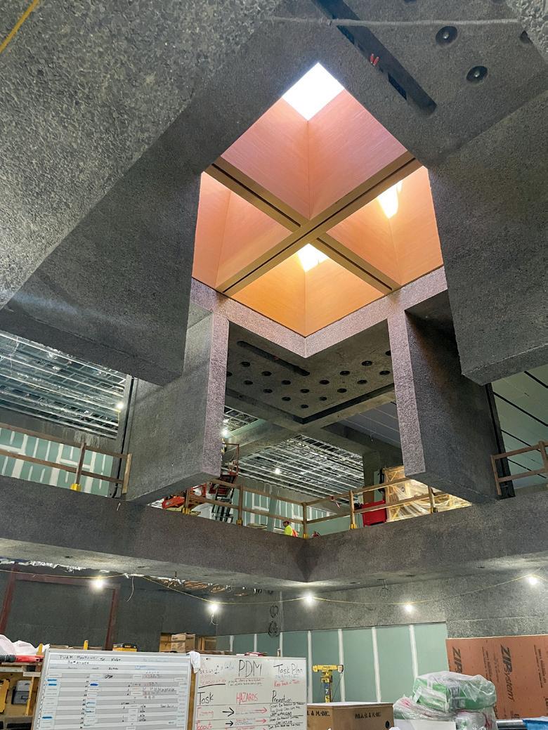
Grand Hall cantilevered blade walls support glulam beams and the skylight above.
The museum's west side features intertwined areas of precast and glazed facades.
the museum’s relationship to the surrounding campus by offering entrance from all four sides of the building. All new construction was carefully sited around the existing Marquand Library, whose interior was renovated while the exterior was retained and reclad with contemporary facade elements to visually and materially integrate it with the expanded museum.
In accordance with the 2018 New Jersey State Building Code, the museum was designed as a Category III structure. Governing design standards included ACI 318-14, AISC 360-16, NDS-2018, and ASCE 7-16. The combination of materials and structural systems pushed the boundaries of each material code and their compatibility with one another where systems interacted.
Structural Systems—New and Existing
Structurally, the building is largely steel framed, with lightweight concrete slabs on composite metal deck supported
by steel beams and columns. Numerous cast-in-place concrete walls, beams, and slabs are distributed throughout the building, many of which are architecturally exposed and sandblasted to reveal aggregate and provide texture. Exposed glulam beams are prominently featured in gallery ceilings, skylights, and major circulation spaces, where they support roof framing while also contributing warmth and visual rhythm to the interiors.
A defining challenge of the project was its integration with existing structures that were required to remain in service throughout construction. The U-shaped footprint of the new construction wraps around the existing Marquand Library, necessitating careful foundation coordination to minimize disturbance to the existing structure. In addition, new construction was built over existing below-grade spaces at both the northeast and southern portions of the site, including the Marquand Library archive and MER rooms to the northeast and the mechanical sub-basement of the 1989 addition to the south. In both cases, the original columns and foundations had been designed to accommodate future expansion and therefore required minimal reinforcement, though detailed verification and coordination were still essential.
Gallery Loading and Future Installations
Museum-specific loading requirements significantly influenced the structural design. Gallery spaces were designed for live loads ranging from 150 to 250 psf to accommodate future flexibility for heavy sculptures and installation loads. Fixed hanging points were incorporated into the structure to support suspended artwork in the ceilings, while exterior terraces were provided with dedicated anchor points to allow for tie-down of outdoor installations. These requirements demanded close coordination between structural, architectural, and curatorial considerations.
Foundations
Subsurface conditions and loading demands led to a combination of foundation systems across the site. Moderate allowable soil bearing pressures of approximately 4,000 psf resulted in the use of large mat foundations beneath heavily loaded concrete walls and steel column clusters. These mat slabs range in thickness from 24 inches to 72 inches and frequently support multiple walls and columns simultaneously. Elsewhere, more conventional foundation systems were employed, including concentric spread footings beneath columns and continuous strip footings beneath load-bearing walls.
Superstructure
Above grade, the superstructure functions as a true hybrid system in which steel, concrete, and timber
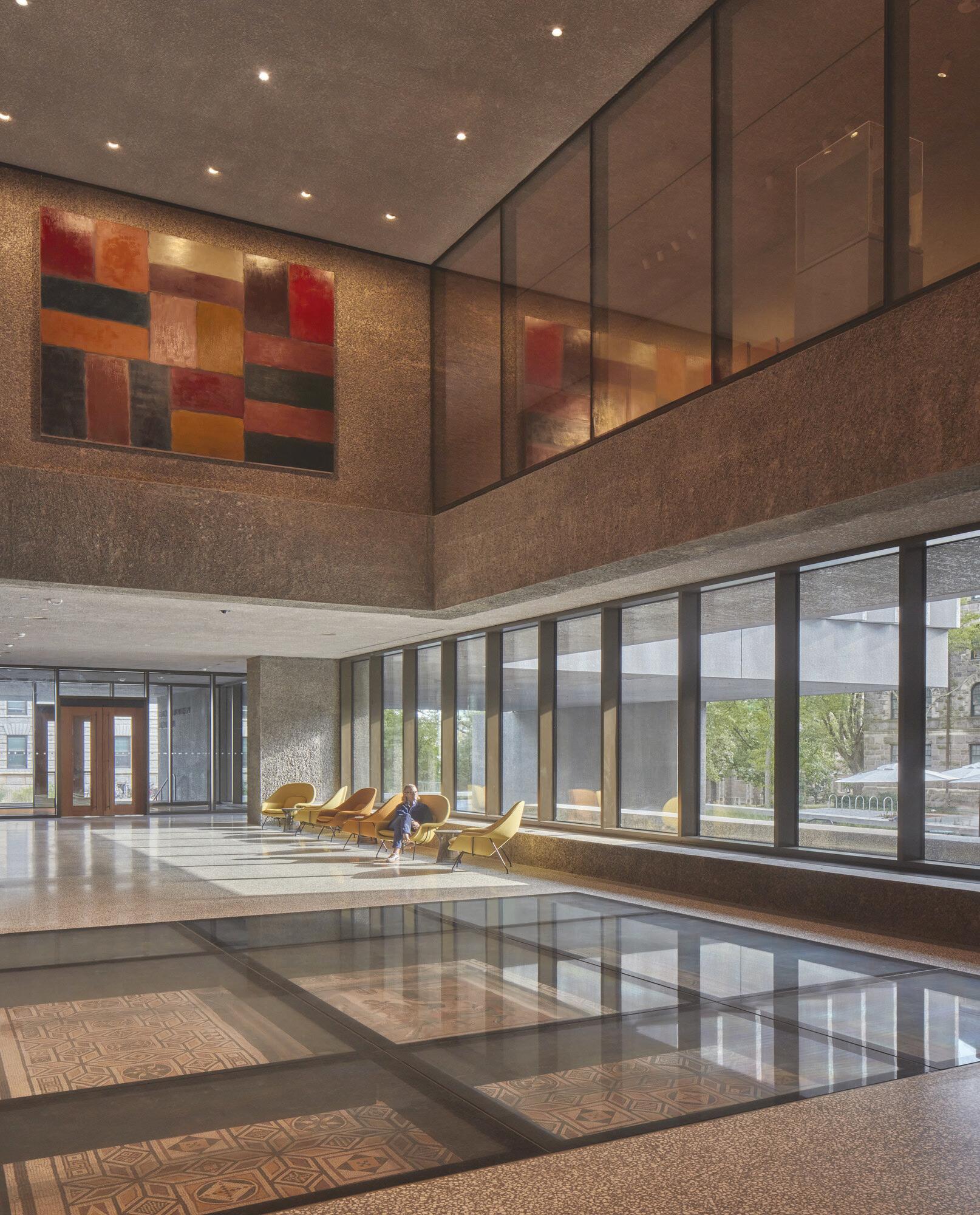
A glass floor-covered mosaic and exposed sandblasted concrete elements add visual interest at the Art Walk.
elements are interwoven to achieve the architectural design intent. Structural steel framing primarily consists of wideflange beams and columns, supplemented by seven distinct types of custom plate girders used to accommodate long spans, cantilevers, and areas with tight architectural depth constraints. Long-span and cantilevered steel framing occurs throughout the building, requiring careful attention to deflection control, cambering, and connection detailing.
Concrete elements were designed using higher-strength mixes to meet both structural demands and architectural exposure requirements. Normal-weight concrete elements typically utilized a baseline compressive strength of 6,000 psi, while select high-demand elements—including major piers, walls, and long-span or cantilevered beams—were designed with strengths up to 8,000 psi. Lightweight concrete with a compressive strength of 4,000 psi was used for composite slabs on metal deck. Most architecturally exposed concrete surfaces were sandblasted to achieve the desired texture and finish.
All exposed glulam members were fabricated from Nordic Lam+ 24ES/NPG stress-grade black spruce. These members were configured as V-shaped beam pairs with depths ranging from 44 inches to 77 inches. Connections to adjacent steel and concrete elements were achieved using lag screws, bolts, and custom steel brackets. A comprehensive char analysis was performed for all glulam members to verify that required fire-resistance ratings could be achieved without the need for additional fireproofing such as a rated enclosure or spray fireproofing.
throughout the building. These included massive moment connection plates (1 to 4 inches thick), bolstered slab supports, large embedded steel plates cast into concrete beams and walls (some with U-shaped or L-shaped plan geometries), saddle and bracket connections supporting high or low glulam beams, and bearing plates designed to accommodate large gravity loads while also transferring diaphragm axial forces into concrete shear walls. To address rebar congestion at heavily reinforced junctions, headed reinforcement, mechanical splice couplers, and Grade 80 reinforcing bars were selectively employed.
The lateral-force-resisting system combines perimeter ordinary concentric steel braced frames with ordinary concrete shear walls. Shifts in bracing locations between floors resulted in numerous offsets within the lateral system, triggering overstrength conditions under ASCE 7-16 seismic provisions and increasing demands on diaphragms and steel connections. To address these load transfers, diagonal steel bracing was incorporated within the floor framing to provide the necessary in-plane force continuity.
The superstructure design also required extensive MEP systems coordination to enable museum-quality climate control requirements. Thousands of beam penetrations (both in concrete and steel elements), wall penetrations, floor penetrations, notches, recesses, steps, jogs, etc. were coordinated between the trades via an intensive BIM coordination process during construction.
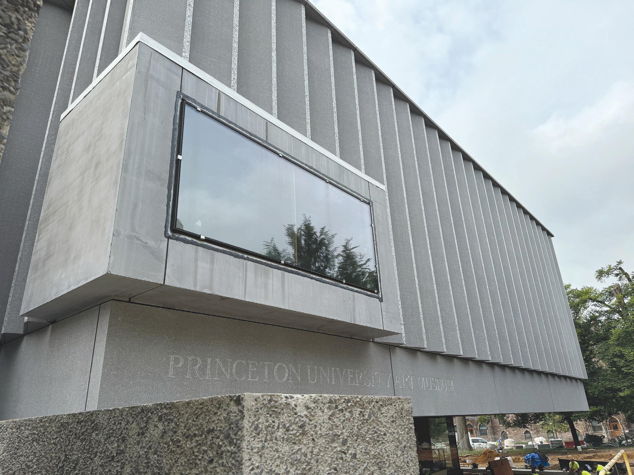
North side "Lens A" with typical sawtooth precast panels beyond is shown.
The building facades further contributed to the structural complexity of the project. Much of the perimeter gallery facade is clad in sawtooth precast concrete panels, each weighing over 30,000 pounds. Extensive deflection coordination was required, particularly where glazed systems are inserted beneath and between the heavy precast panels. Ten dedicated sheets of deflection diagrams were developed as part of the contract documents to address overall movement and differential movements between floors under pattern live loading. In areas where precast panels are supported between floors over glazing—most notably at the airy “lenses” found between the largely opaque pavilion galleries—secondary steel tube frames were introduced to resist gravity and wind loads of the facade panels. These tube frames were installed using slotted connections at the top to better isolate the glazing and secondary framing from movement of the primary structure above.
3rd Floor Restaurant and Grand Stair
One of the most structurally intricate areas of the building is the third-floor restaurant and grand stair zone. The architectural intent for this space required a large clear span at the second floor, necessitating that the third-floor restaurant framing be suspended from the roof structure above. Eight 2½-inch-diameter solid steel architecturally exposed structural steel (AESS) rods hang the third-floor framing from two 48-inch-deep plate girders spanning 81 feet between columns and girders at the roof level. This area of the building also incorporates an architecturally exposed concrete grand stair with bronze-framed guardrails, a custom cast-in-place concrete hearth, multiple column transfers, glulam framing supported by orthogonally bent W18 steel beams to accommodate slab elevation changes, and cambered W40x593 beams designed to minimize long-span deflections.
The Grand Hall serves as the museum’s signature space, rising three stories and accommodating a variety of public uses. Structurally, it is defined by 24-inch-thick cast-in-place concrete slabs spanning to a ring of concrete walls at the first floor, and flying buttress-style “blade walls” cantilevering from the second floor. Massive concrete beams—some measuring up to 72 inches wide by 72 inches deep—ring the second- and third-floor openings, providing the stiffness required to control deflections while creating deep soffits that visually layer the space. The hall is capped with glulam beams supporting a skylight that introduces natural light and warmth into the interior. Lighting and MEP systems are seamlessly integrated into the concrete structure through carefully coordinated notches, recesses, and web penetrations.
West Side Pavilion Galleries
Some of the most significant structural challenges were encountered at the west side pavilion galleries. These galleries feature long cantilevers in multiple directions and asymmetrical concrete wall configurations supporting the volumes above. The second-floor steel framing beneath each gallery consists of W33 and W36 beams (averaging 250-300 lb/ft) and 36-inch deep plate girders, while Pavilion 2 includes a 52-inch-wide by 125-inch-deep cantilevered concrete beam supporting a 44-foot cantilever. Six rows of fourteen #10 reinforcing bars were required at both the top and bottom of the beam to control deflections and meet strength demands.
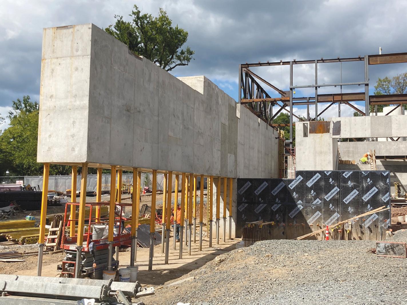
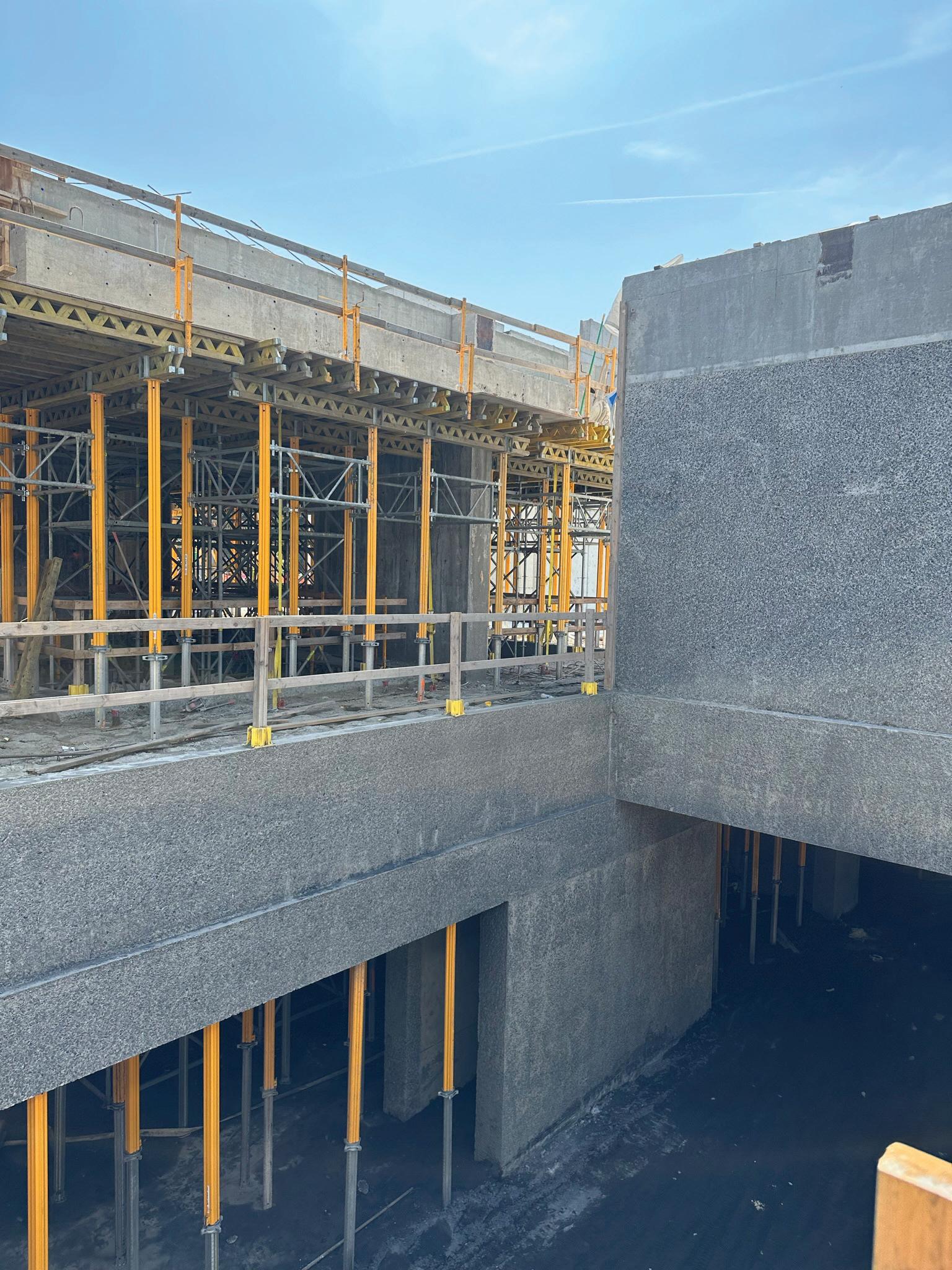
Shoring and Sequencing
Temporary shoring and construction sequencing were critical to the successful execution of the project, particularly
Steel framing and glulam beams are erected for the west side pavilion galleries 1 & 2 during construction.
in areas such as the Grand Hall, west side galleries, glulam ceilings, and other zones with intertwined steel and concrete framing. Close coordination with the shoring engineer (Plan B Engineering), as well as with the construction manager and structural subcontractors, was required to ensure diaphragm continuity, control deflections, and maintain compatibility between site logistics, schedule, and structural performance. These challenges were further compounded by the extensive MEP coordination required to achieve museum-quality climate control, which necessitated hundreds of penetrations through beams, walls, and slabs.
Marquand Library Renovation
As the new construction portion of the project neared completion, the last step for the complex was to unify the exterior of the last remaining existing structure on the site (the Marquand Library) with the new building. The primary scope of this work consisted of recladding the building in thinner precast concrete panels and modern glazing, along with targeted structural infills and adjustments to rooftop massing and transparency.
Conclusion
Following art installation, the Princeton University Art Museum officially opened to the public in October 2025. The completed museum has quickly become a vibrant destination for visitors of all ages, showcasing a collection of more than 117,000 artworks and artifacts. After more than a decade of planning and design, Princeton University and the broader public have gained a new architectural and cultural landmark at the heart of the campus. ■
(jason.tipold@tylin.com)
Jason Tipold is a Principal at TY Lin, in the NYC office of the Buildings Sector (formerly Silman). He has been a structural engineer at TY Lin/Silman since 2007 and has a wide range of experience in both new construction and existing buildings.
Temporary shoring is in place for Level 2 cantilevered concrete beam under pavilion gallery 2.
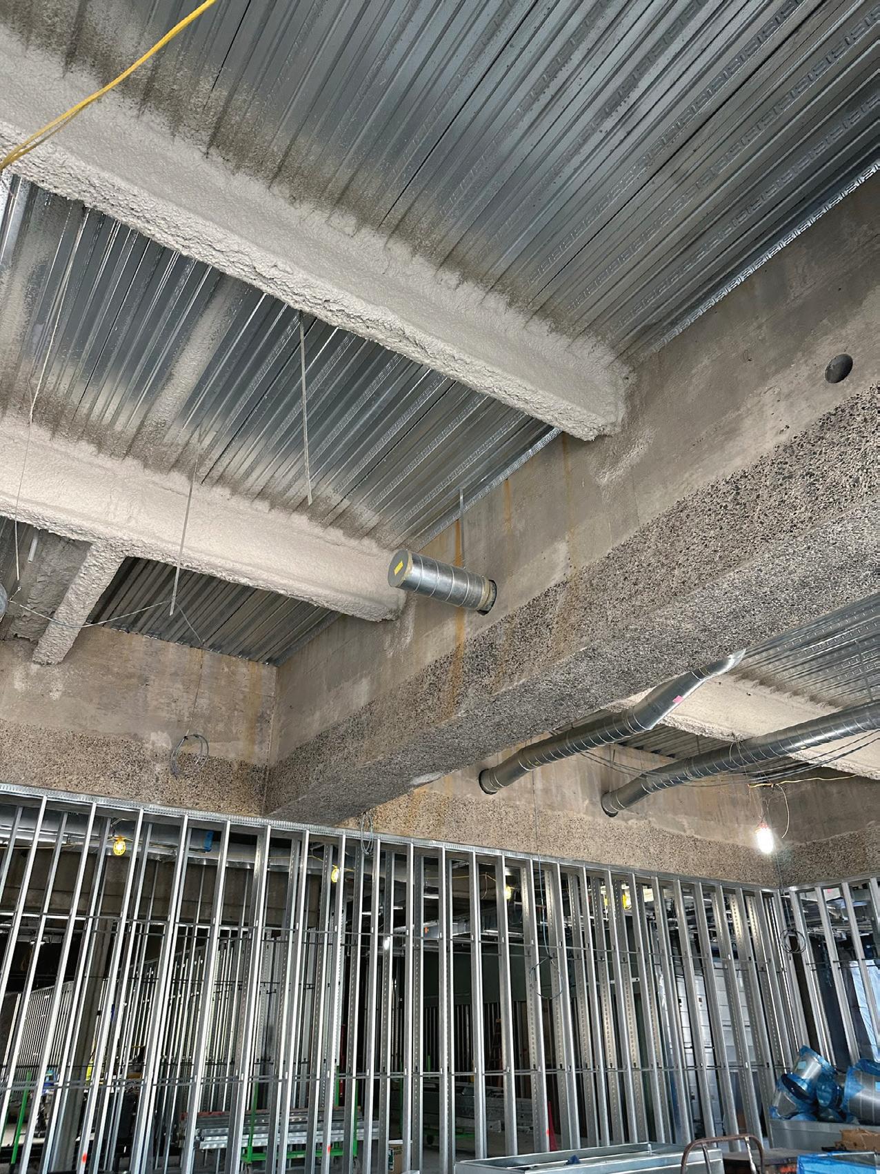
Exposed sandblasted concrete walls and beams at the Art Walk are shown during construction.
Primary sandblasted exposed concrete beams at Level 3.
Bridging Nature & Structure: Creating a Gateway to Bentonville’s Trail System
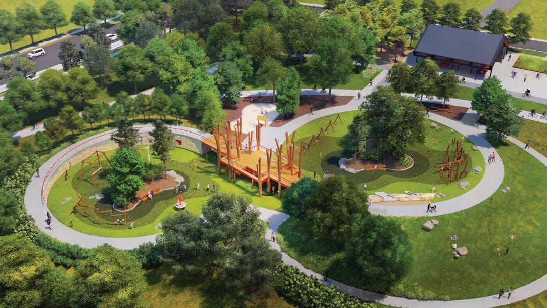
A harmony of structure and landscape defines Bentonville’s 8th Street Gateway Park, where innovative engineering creates a nearly two-thirds-mile elevated loop and nature-focused spaces throughout the 110-acre site.
By Aaron Kilgore, PE, Austin Curnutt, SE, PE, and Bryce Crady, PE
Bentonville, Arkansas, has quickly become a mecca for culture, workforce talent, and outdoor recreation, with its population nearly doubling over the past decade. As a mountain-bike hub for Northwest Arkansas, the city is making its largest public space investment to date: the 8th Street Gateway Park. The park will serve as the centerpiece of the Bentonville Parks system and the western anchor of a 25-mile trail network, creating a destination for outdoor activity for both residents and regional audiences.
Serving as the structural engineer of record, Apex Engineers collaborated with PORT Urbanism, the Project Lead Architect and Lead Landscape Architect, as well as Polk Stanley Wilcox, the Architect of Record, to bring the park’s vision to life, creating structures that harmonize with, rather than compete against, the natural environment. The park is divided into three zones—West Park, East Park, and the Park Core—each offering unique landscape characteristics and recreational opportunities, requiring unique structural solutions. Its centerpiece, the Gateway Ring, forms a nearly two-thirds-mile pedestrian loop connecting key areas of the park while providing scenic overlooks that showcase the site’s rich natural character.
During the master planning process, the community played a central role in shaping the park’s vision. More than 300 people attended a Design Kickoff and Community Input Event, and the team collected over 300 pieces of feedback through comment cards, large-format maps with sticky notes, and preference dots placed on precedent imagery boards.
East Park
The structural scope within the East Park area of the project consisted of a comfort station, five boardwalks, and the Gateway Ring, which features two elevated pedestrian trails and two long-span truss bridges.
The comfort station is a 240-square-foot structure with CMU walls and a gabled roof made from cold-formed steel trusses. The walls and roof are clad with an architectural metal panel that is intended to visually match the weathering steel being used for the elevated pedestrian trail structures.
The boardwalks are constructed with pre-cast hollow core concrete planks and a 4-inch thick topping slab. They are at-grade and span across areas of the landscape which are
depressed to allow water to flow across the site. Two of the boardwalks are single-span, two are three-span, and one is four-span. The multi-span boardwalks have cast-in-place concrete intermediate beams supported by round concrete pedestals and shallow foundations.
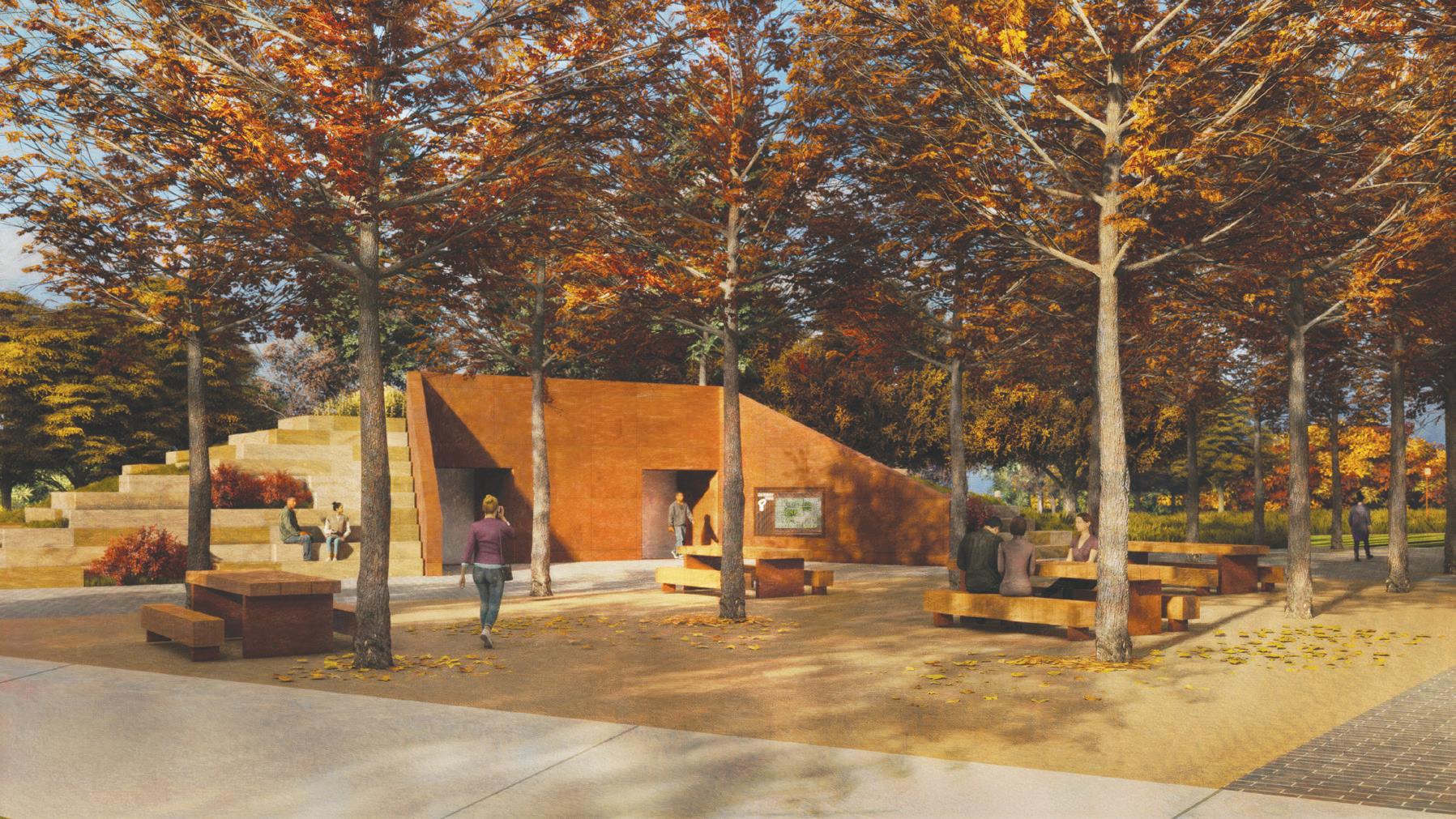
West Park
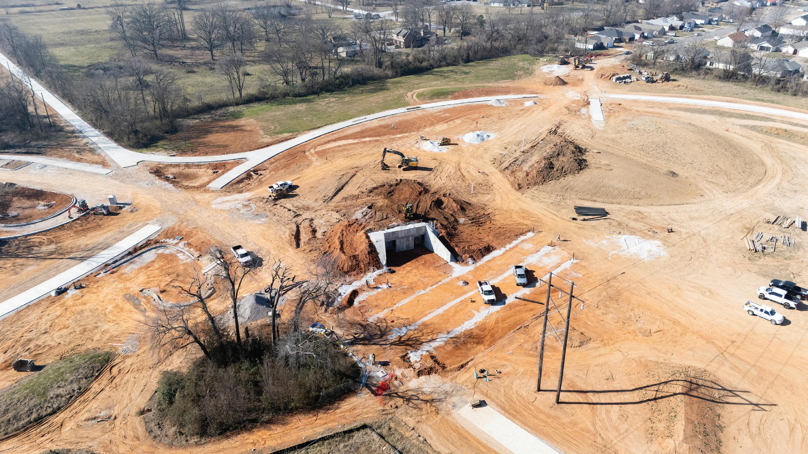
The structural scope within the West Park area of the proj ect consisted of a 442-square-foot, partially underground comfort station. The all-concrete structure, including lid, walls, and foundations, was designed to support 24 inches of soil fill and pedestrian terrace live loading atop the structure. Key architectural features include the sloping retaining walls forming the walkway to the entrance. The top of wall elevation varies from 15 feet 6 inches above top of foot ing to 4 feet 2 inches. The walls use two thicknesses—12 inches below grade to retain soil and 6 inches above grade for fall protection. The walls are clad with architectural metal panels that match the East Park Comfort Station, reinforcing a cohesive design language throughout the park.
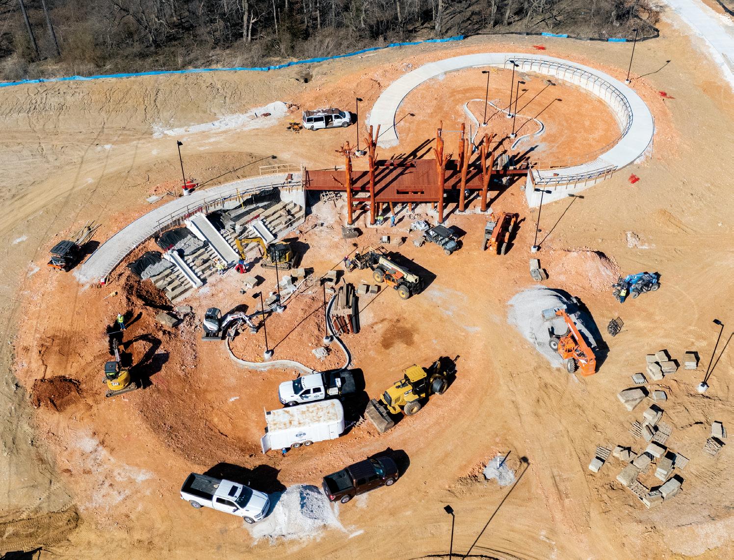
The Gateway Ring in Bentonville's 8th Street Gateway Park features elevated trails and two long-span bridges. (Photo courtesy Crossland Construction.)
West Park Comfort Station (exterior rendering shown here) is an all-concrete structure that is partially underground and designed to support 24 inches of soil fill and pedestrian terrace live loading.
The Park Core includes a central pavilion and retaining walls forming two bowl areas around a one-acre destination playground. The retaining walls range from 4 to 12 feet in height. One unique feature of these walls is the masonry veneer, which uses custom-shaped blocks to form bouldering walls.
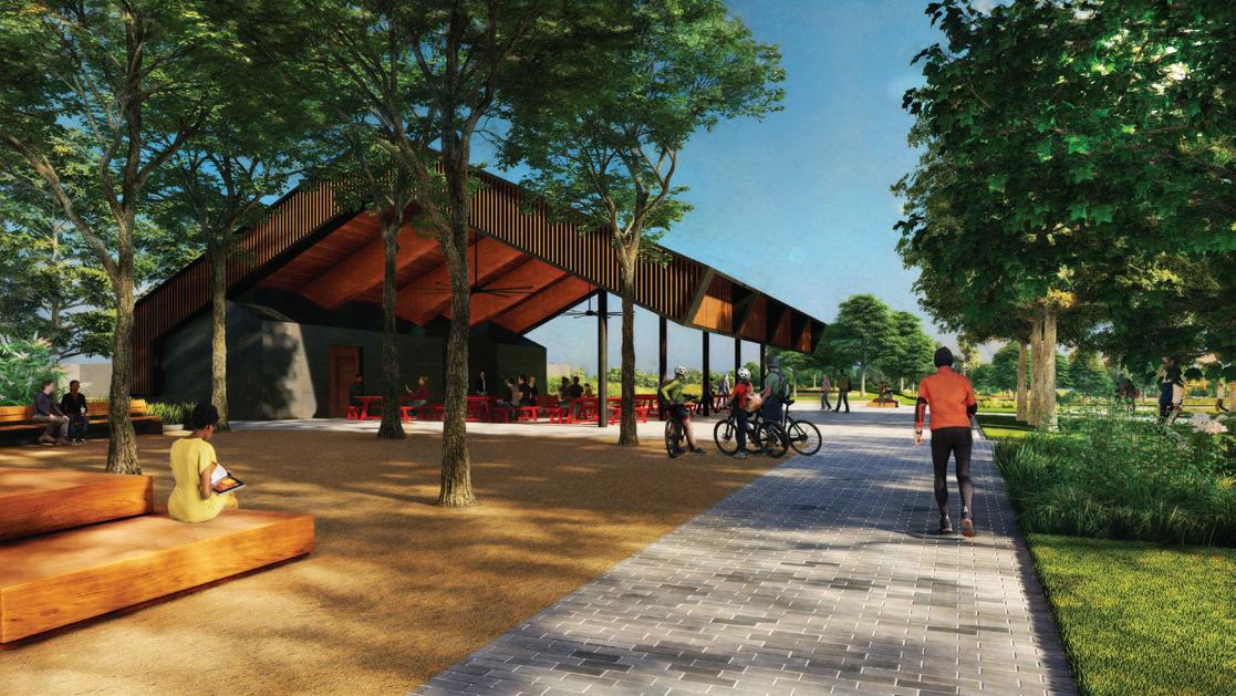
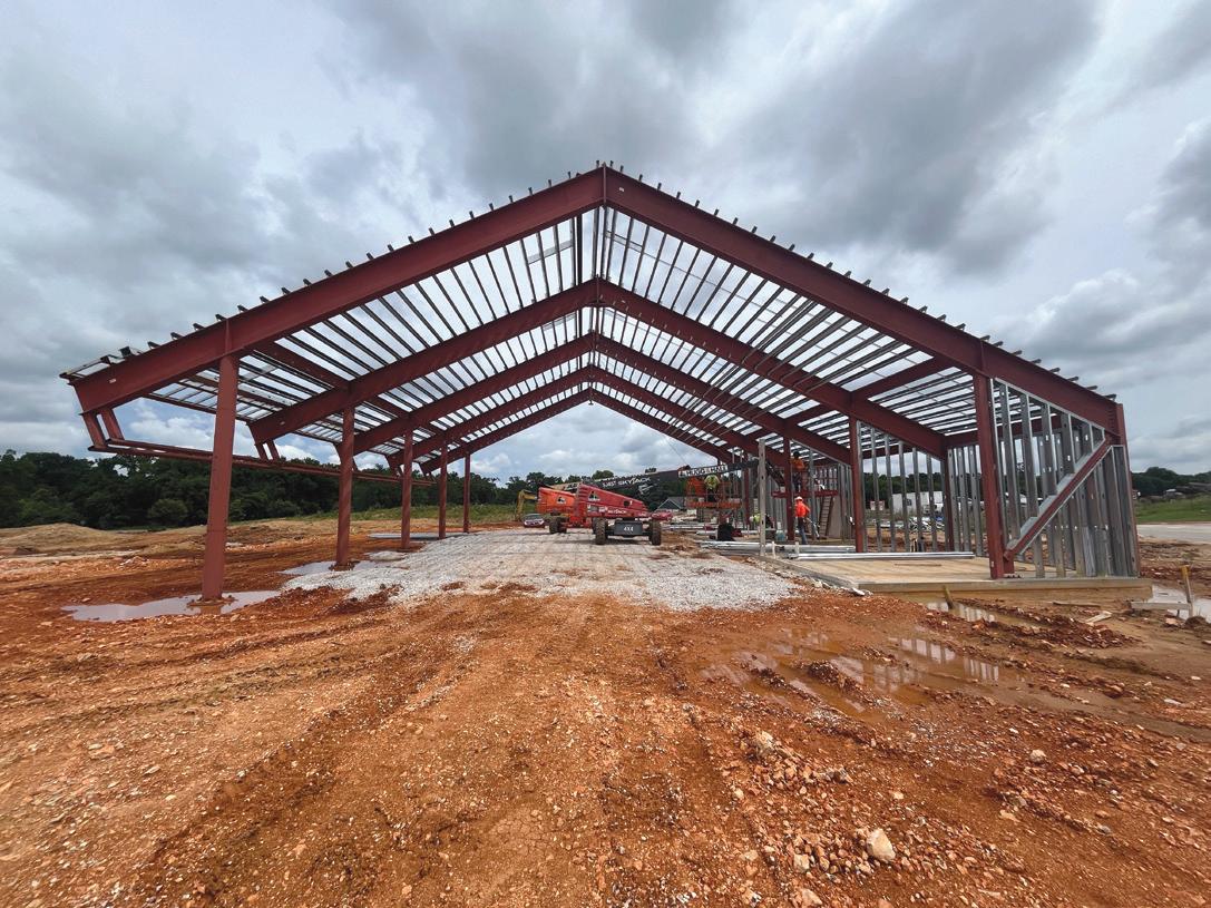
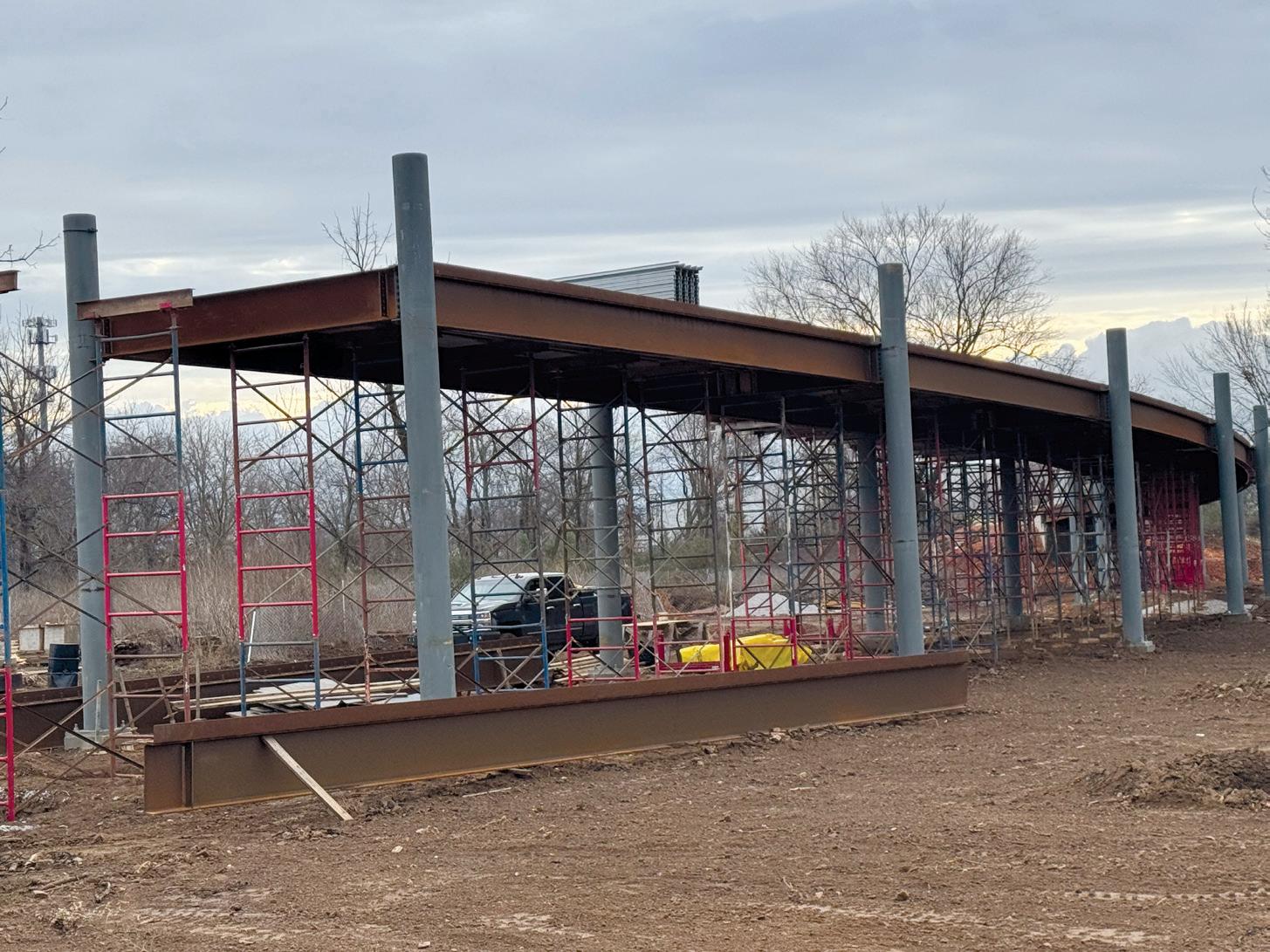
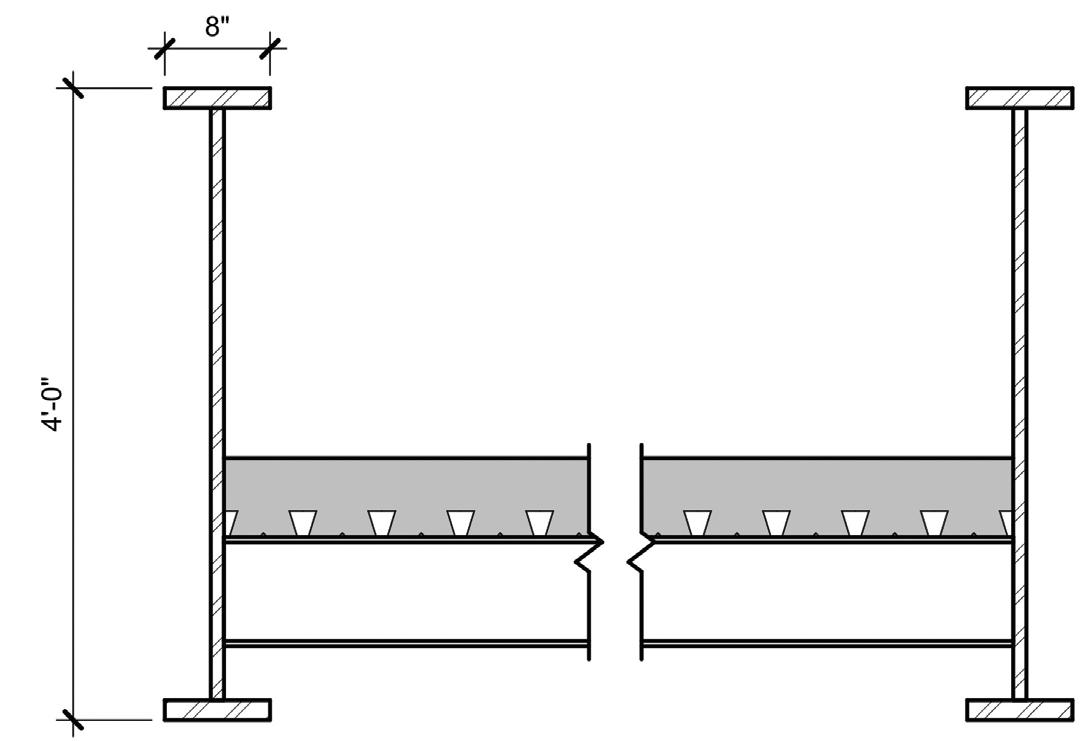
The Park Core Pavilion is a 4,052 square-foot open-air structure constructed with hot-rolled steel frames and cold-formed metal stud wall framing. Early in design, the client expressed interest in preserving and converting the existing barn structures into a pavilion. However, the buildings were not in a condition that allowed for economically feasible reuse, leading the design team to develop a new design that honored the barns’ character while meeting modern structural requirements.
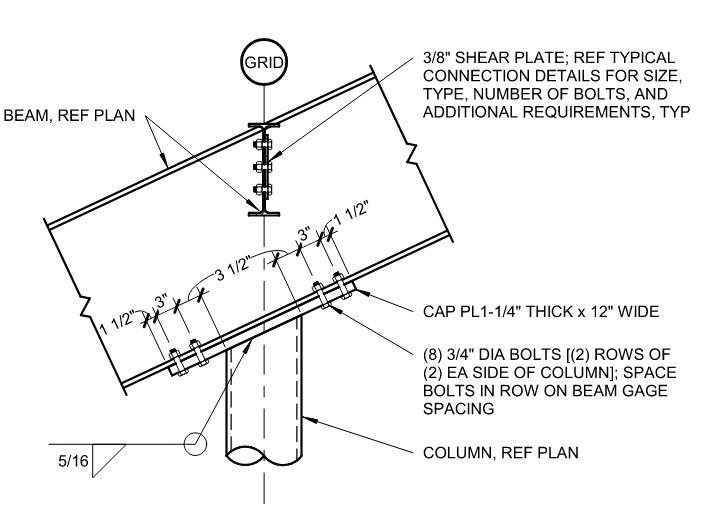
Lateral forces on the pavilion are resisted by a combination of steel cantilever columns in the exposed public assembly space and steel braced frames in the back-of-house spaces. The primary challenge for the bent frames was their length. The bent frame could not be
The Destination Playground and Park Core Pavilion (rendering shown above, under construction at right) features retaining walls with a masonry veneer. (Construction photo courtesy Crossland Construction.)
The Park Core Pavilion (rendering shown at left and under construction at right) is built with hot-rolled steel frames and cold-formed metal stud wall framing. (Construction photo courtesy Crossland Construction.)
Field-bolted end plate moment connections were secured to the cantilever columns in the Park Core Pavilion with field-bolted cap plates.
shipped to site as a single piece. The 5 5/8 inches per 12 inches roof slope resulted in an approximately 15 feet 6 inches change in elevation from eave to peak.
To accommodate standard-length trucks and simplify construction, the design team spliced the frame beams at the peak using a field-bolted end plate moment connection and secured the frame-to-column connections with field-bolted cap plates.
Gateway Ring
The Gateway Ring forms the focal point of the 8th Street Gateway Park. This nearly two-thirds-mile loop includes approximately 880 feet of elevated trail built on a 520-foot centerline radius with a longitudinal slope. Two separate elevated trail structures—the East Gateway Bridge and West Gateway Bridge—span 372 feet and 508 feet, respectively, while the remainder remains at grade.
Each bridge features a long-span dovetail metal deck topped with a 6-inch concrete slab. Radiused wide-flange beams with composite studs connect to wide-flange crossbeams, providing lateral stability through moment connections to round HSS columns. Each elevated
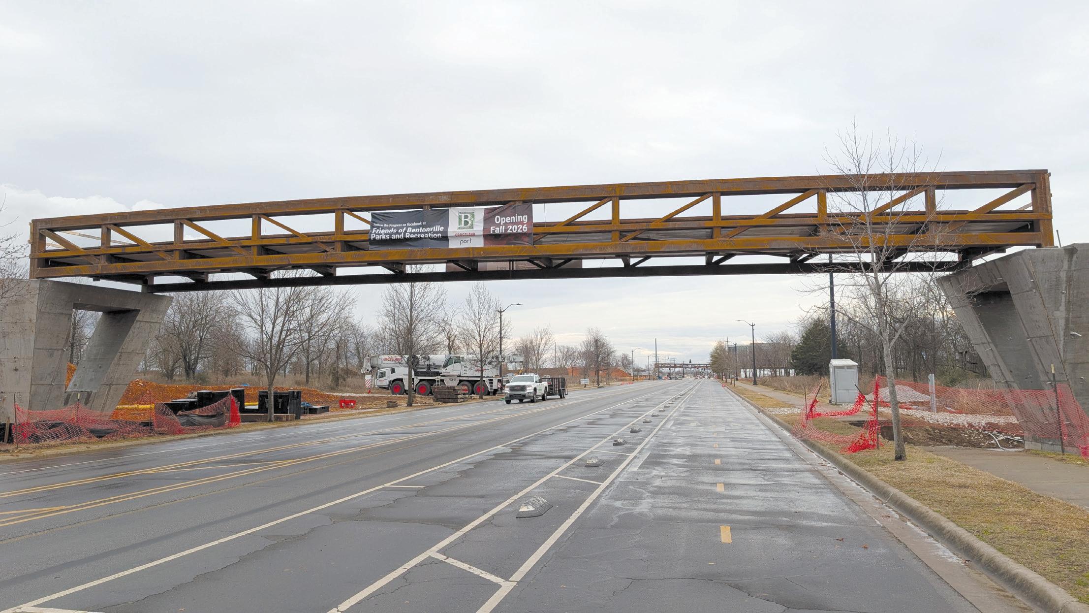
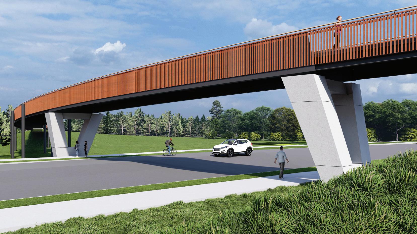
Two truss bridges (under construction above and in rendering at left) span 110 feet over 8th Street on the west and east sides of the Gateway Ring. (Construction photo courtesy Crossland Construction.)
trail section includes a 7-foot cantilevered overlook for scenic views.
The truss bridges span approximately 110 feet across 8th Street on both east and west sides of the ring. Concrete abutments support the bridges, and columns slope transversely and longitudinally from pier caps atop nine 24-inch-diameter piers. Elevated trail columns rest on 36-inch-diameter drilled piers with pier caps.
The structures were designed in accordance with the American Association of State Highway and Transportation Officials (AASHTO) Bridge Design Specifications and the AASHTO LRFD Guide Specifications for the Design of Pedestrian Bridges. The design live load is 90 pounds per square foot, with wind loads determined per the AASHTO Bridge Design Specifications. Additionally, a 10,000pound design vehicle was considered.
Elevated Trails
A challenge for the design team was determining how to deliver a structure meeting the architectural intent of the owner while being mindful of the budget constraints of the project. The design team went through a few different iterations of the structure before ultimately landing on the final design.
For the elevated trails, the architect envisioned a dynamic “skipping” effect, offsetting the inner and outer columns and using hollow tube beams for the edge supports. This offset created a structural challenge: diagonal members were required between columns to resist lateral forces, and intermediate transverse beams were needed to brace the diagonals against axial loads. Though technically feasible and allowing for a shallower composite deck, the approach significantly increased steel tonnage and overall cost.
Working closely with the architect and design team, Apex Engineers guided a value engineering review that resulted in the final solution, wide flange edge beams with wide flange crossbeam moment frames supporting a long span dovetail deck, balancing structural efficiency, cost, and the aesthetic vision.
The contractor identified the time and cost associated with corrosion protection as a challenge. The original specifications required a painted steel system; however, in response to the contractor’s concerns, the design team collaborated with them to identify a more economical and durable solution. Weathering steel was ultimately selected to provide long-term corrosion protection while maintaining the architectural intent and project budget.
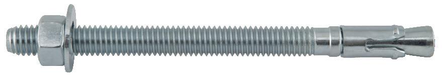
ASTM A588 steel was specified for all wide-flange shapes and angles, and ASTM A847 was specified for rectangular and square hollow structural shapes. Because round HSS shapes are not available in a weathering steel grade, the round HSS columns supporting the elevated trail’s cross beams required a paint system for corrosion protection. All of the non-weathering material for the shear tabs and flange plates connecting the cross beams to the round HSS columns required a protective coating at the contact surfaces between the plates and the beam to prevent galvanic-like corrosion of the flange plates and shear tabs. All bolted connections utilize Type 3 bolts.
Thermal expansion also had to be considered during the bridge design process. Expansion joints and slip-joint beam connections were utilized at every other bay, approximately every 80 feet, to allow for thermal expansion along the elevated trail. Additionally, an expansion joint was specified at each end of the truss bridges, and baseplate connections allowing for thermal movement were provided.
Vibration control was a top priority for the structural team. Using AISC Design Guide 11: Vibrations of Steel-framed Structural Systems Due to Human Activity , the engineers determined acceptable
frequencies for both the elevated trails and the truss bridges. Because AASHTO’s vibration criteria for pedestrian bridges are less strict, the team gained added confidence that their design went above and beyond to ensure a comfortable and safe experience for trail users.
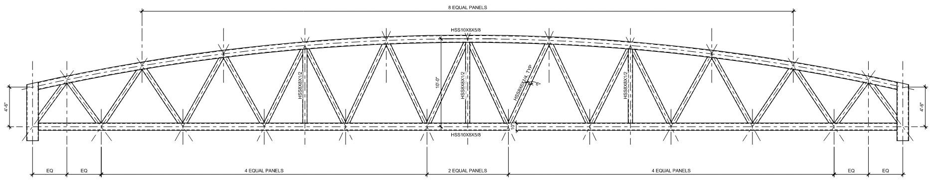
Truss Bridges
The two truss bridges spanning 8th Street went through multiple design iterations before the final concept was selected. The architect initially proposed a 48-inch-deep plate girder half-through bridge with 8-inch-wide flanges. However, early analysis, combined with input from AISC’s National Steel Bridge Alliance, showed that this approach was not economically feasible within the architectural constraints—the flanges would likely have needed to be twice as wide as architecturally desired.
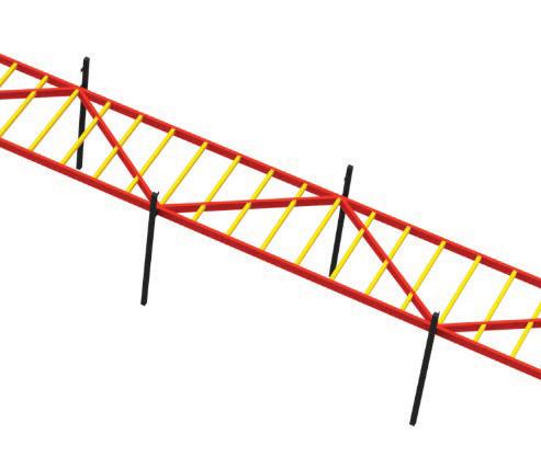
The next concept the team explored, and ultimately chose, was a half-through truss bridge. The team considered an arched truss, which ranged from 4 feet 6 inches to 10 feet between chord centers, but it did not match the architect’s design intent. Therefore, a shallow parallel chord truss was chosen.
Apex Engineers ran a dynamic analysis using RISA-3D to determine
Shown is a design concept for the elevated trails.
Construction progress shows the final design with crossbeams. (Photo courtesy Crossland Construction.)
Shown is the initial plate girder half-through bridge concept.
Above is the arched truss concept in which the truss ranged from 4 feet 6 inches to 10 feet between chord centers.
the bridge’s modal frequencies, which exceeded the requirements of LRFD Guide Specifications for the Design of Pedestrian Bridges.
The structural design of Bentonville’s 8th Street Gateway Park required a deep understanding of the project’s vision and close coordination with the full project team to create structures that blend with the landscape and elevate the visitor experience. Apex Engineers partnered with the project architects and contractor to select materials that naturally fit the surroundings while delivering a cost-efficient design that remained within budget. Ultimately, the park’s value will be reflected not by its engineering feats, but in how it brings people together, providing space for recreation, gathering, and meaningful connection to nature. ■
Aaron Kilgore, PE is an Associate & Project Manager at Apex Engineers and served as the Project Manager for this project. He brings extensive experience in the design of diverse structural systems across a wide range of construction types.
Austin Curnutt, SE, PE is a Senior Project Engineer at Apex Engineers and served as the lead design engineer for this project. He is dedicated to partnering closely with clients to develop innovative structural solutions that support their vision.
Bryce Crady, PE is the Principal & CEO of Apex Engineers and served as the stamping engineer for this project. With more than 20 years of structural engineering experience, he leads Apex’s three offices and guides projects nationwide.
A shallow parallel chord truss elevation was ultimately chosen because it best matched the architect’s design intent.
The partially underground West Park Comfort Station is shown under construction. (Photo courtesy Crossland Construction.)
codes and STANDARDS
Opening the Door to Fire-Rated Enclosures
Fire-rated glazing gives more design choices for stairways and elevator enclosures, but they must adhere to code-driven, fire-rated standards.
By Devin Bowman
Building codes require all commercial buildings to defend occupants and means of egress routes in the event of a fire. The specifics for these requirements depend on several factors, from the building’s full height and proximity to other buildings to the location and construction of individual elements within the building itself. While traditionally out of the scope of structural engineering, analyzing and designing a building for fire safety is increasingly interconnected with structural systems. For example, due to lot line restrictions and brand alignment, an Audi dealership in Birmingham, Michigan, needed a fire-rated exterior curtain wall. This assembly was anchored to multiple structural points on the floor and ceiling. With the added weight of fire-resistance-rated glazing, the full assembly
needed additional structural analysis to ensure the anchoring and spans were within tolerances for appropriate structural loads. Further, for larger curtain walls, secondary supports might need to be spliced into the assembly. Inside a building, fire walls, fire barriers, and fire partitions all have different structural needs, which may necessitate the analysis of a structural engineer.
This interconnectedness of structural and non-structural components and the varying degrees of structural bearing fire-rated systems can provide means, as Dr. Frederick W. Mowrer writes in an article from the January 2018 issue of STRUCTURE, “it is useful for [structural engineers] to have at least a basic understanding of building fire safety issues.”
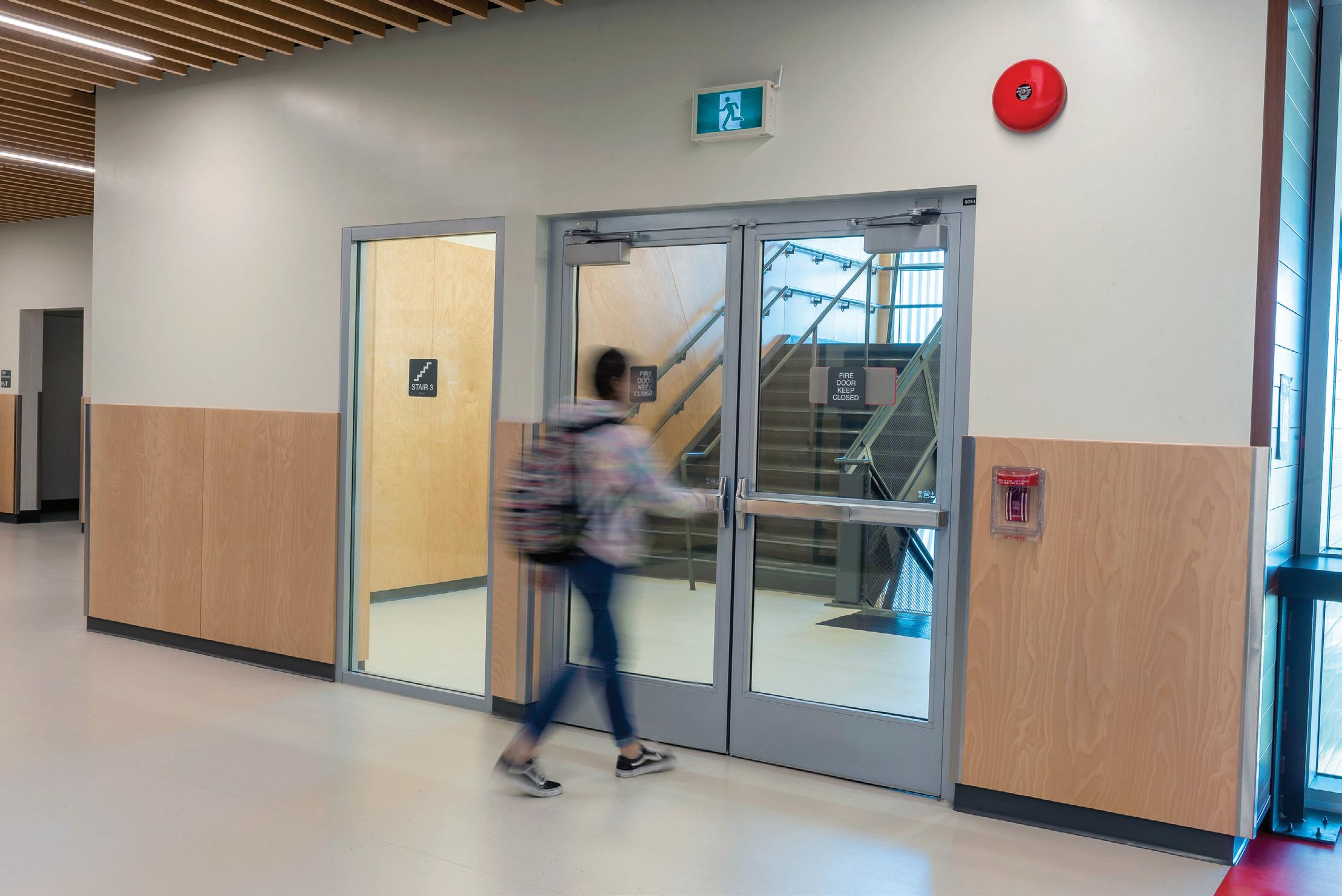
Fire-rated glass doors support intuitive wayfinding while meeting code requirements. (Photo courtesy of TGP)
Connected to and influenced by structural components as well as integral to a means of egress system, enclosures for stairways and elevators must achieve code-driven, fire-rated standards. These code-compliant systems do not just contribute to certificate of occupancy; they also meet a baseline of occupant safety. When structural engineers can contribute to both structural efficacy and occupant safety when designing and analyzing these enclosures, they can deliver more value to the full project team and streamline planning phases. That said, there are many options for code-compliant fire-rated enclosures.
In the past, building professionals may have been limited to opaque materials which made designing these parts of the built environment purely functional. With the advent of fire-rated glazing, the potential in stairway and elevator enclosure design saw significant expansion to its ability to support occupants with daylight, visual connection, and intuitive wayfinding. However, more design choices for these parts of a means of egress system lead to more opportunities to unintentionally specify a non-code-compliant system.
When determining fire-rated requirements for enclosures, start by analyzing the building’s broader context before drilling down into wall and opening specifications, as each component’s rating is contingent on its surroundings. Offering a basic overview of firerated requirements for various elements of the built environment, this article will use the 2024 edition of the International Building Code (IBC) for discussing rating requirements, but project teams are encouraged to consult local codes and contact an Authority Having Jurisdiction (AHJ) to clarify any ambiguities or amendments.
code-allowed alternatives, it is encouraged to consult with an AHJ to assess the applicability of a proposed alternative and fully understand the life safety outcomes of such a tradeoff. With these distinctions in mind, project teams can turn toward the individual elements of enclosures.
Full Building Code Overview: General Rules and Reasoning
When determining the code-driven requirements for enclosures, consider the full building’s context first. For instance, if a building is located within a certain code-defined distance (usually 10 feet or less) from the lot line or other buildings on the same lot, its exterior walls and openings will need to be fire-rated. This requirement is to mitigate instances in which fires spread from one building to the next.
In addition to location, the height of a building, and subsequently the number of stories its shaft enclosures connect, plays a role in determining fire-rated design requirements. According to Section 713.4 of the 2024 edition of the IBC, shaft enclosures connecting four or more stories will need their walls and barriers to achieve a fire-resistance rating of not less than 2 hours. Enclosures connecting less than four will need a minimum of 1-hour fire-resistance ratings. The discrepancies between ratings allow more time for evacuation in taller buildings and compartmentalize a fire on its floor of origin.
While this section includes an exception for applications of reduced fire-resistance ratings under certain conditions, this exception is for high-rise building enclosures “other than interior exit stairway and elevator hoistway enclosures” (IBC Section 403.2.1.2). With exemptions and
Differentiating Walls, Barriers, and Partitions for Enclosures
Although IBC Section 713.4 seems to make determining the fire-resistance-rating requirements for enclosures straightforward, building teams need to account for other considerations, specifically whether a wall is a fire wall, fire barrier, or fire partition. These distinctions can impact the rating requirements for enclosures. All
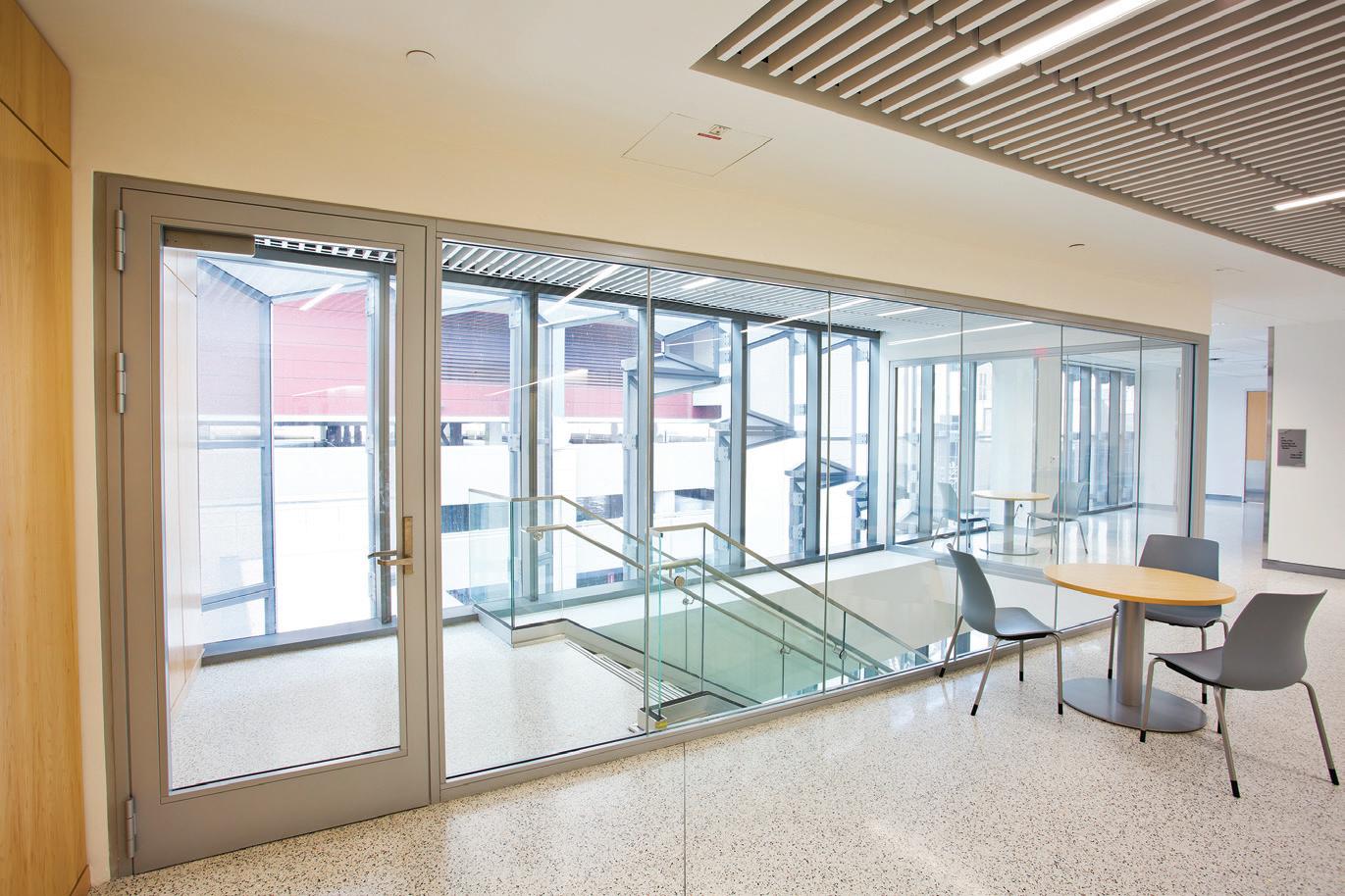
Fire-resistive-rated glazing assemblies can meet fire barrier requirements which impact the ratings of opening protectives. (Photo courtesy of TGP)
Building proximity to other buildings or lot lines may require fire ratings in exterior openings. (Photo courtesy of TGP)
three fire-resistance-rated assemblies are designed to restrict the spread of fire and may include opening protectives.
The main distinction between these three elements is where they terminate. Often used to separate spaces within the same space, fire partitions terminate at the floor and ceiling. They are primarily used for corridor walls and tenant separations. As such, a fire partition likely would not be part of an enclosure.
Fire barriers are more robust and must extend from the floor to the fire-resistance-rated floor-ceiling assembly (or roof) above it. These barriers may serve as walls for entering a stairway enclosure and are subject to the rating requirements listed in IBC Sections 713 (shaft enclosures), 711 (horizontal assemblies), or 707 (fire barriers) or all three.
ENGINEERED TO LAST. PROVEN TO PERFORM.
Fire walls are the most stringently rated of the three; they are designed for structural stability, so they remain standing even if the structure on one side collapses. These walls extend the full height of a building (foundation through the roof) and require a rating in accordance with their occupancy as outlined in IBC Table 706.4, Fire Wall Fire-Resistance Ratings.
Specifically for elevator and stairway enclosures, determining if an opening is in a fire barrier or a fire wall will impact its rating and the ratings for any opening protective within the wall in question.
Specifying Appropriate Opening Protectives for Fire-Rated Enclosures
First, opening protectives, whether they are doors, windows, or otherwise, will need a rating that is appropriate within their barrier or wall. IBC Table 716.1(2), Opening Fire Protection Assemblies, Ratings and Markings, details the exact requirements for door assemblies given the required wall assembly rating in hours. According to this table, most door and window assemblies will need to have fire-resistance ratings equal to their wall assemblies’ ratings. There are a few variations:
• Openings in exterior, fire-rated walls.
• Doors, sidelites, transoms, and vision panels in 2-hour fire-rated walls and enclosures.
• Fire doors in 4-hour fire-rated walls. If an enclosure includes an exterior wall that is rated for two or three hours, its openings will likely need to be fire-rated for 90 minutes. For 1-hour rated exterior
walls, openings will need a 45-minutes rating. Doors, sidelites, transoms, and vision panels in enclosures with 2-hour fire-rated interior walls can meet code-driven requirements with fire ratings of 90 minutes. For both exceptions, the rationale is that door and window assemblies will be free of obstruction (like boxes and furniture), which is considered fuel, so these assemblies will be less likely to experience the most intense heat and flame conditions in a building fire.
This means, for tall buildings with connected egress stairways and elevator shafts, most opening protectives will need to achieve a 90-minute fire rating. Though rare for enclosures, 4-hour rated walls only require 3-hour fire-resistance-rated doors, but its sidelight or transom assembly will need a 4-hour rating.
When glass is incorporated into these openings as vision lites, sidelites, and transoms, they should be tested and rated in accordance with ASTM International’s standard ASTM E119 or UL Solutions’ standard UL 263 for fire-resistance. For full-lite fire doors, the National Fire Protection Association’s standard NFPA 252 is required. Further, for door assemblies that must also meet temperature-rise requirements, NFPA 252 adds a stipulation that, for the first 30 minutes of the fire test, the non-fire side of the door must limit the ambient temperature to no more than 250F, 450F or 650F—with 250F allowing the least amount of heat transfer. For openings that are fire-protection-rated, NFPA 257 and UL 9, UL 10B or UL 10C are the standards listed in the IBC for determining
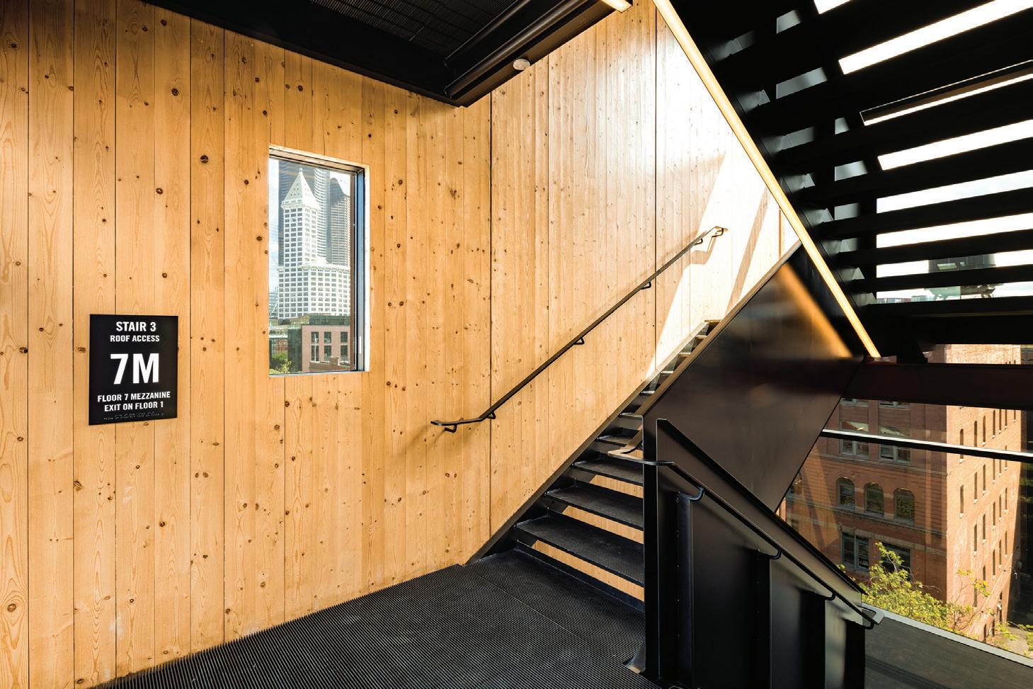
Fire-rated curtain walls connect to structural elements and, due to their weight, may need additional structural analysis. (Photo courtesy of TGP)
Fire-rated curtain walls for this multi-story stairway attach to structural members at multiple points across their spans.
(Photo courtesy of TGP)
The IBC has a standard fire label that abbreviates which tests a glazing assembly have passed and which application uses are appropriate for the assembly.
• For ASTM E119 or UL 263:
W—meets wall assembly criteria.
FC—meets floor/ceiling criteria.
• For NFPA 257 or UL 9:
OH—meets fire window assembly criteria including the hose stream test.
• For NFPA 252 or UL 10B and UL 10c:
D—meets door assembly criteria.
H—meets fire door assembly hose stream test.
T—meets 450F temperature-rise criteria.
• Numbers after the letters indicate the time in minutes an assembly can provide fire resistance or fire protection.
As an example, if a glazing assembly has “D-H-T-120 OH-120 W-120” on its label, it can be used as a 120-minute fire-resistancerated door, window or wall, has passed the hose stream test and meets temperature-rise criteria.
Size limits often apply to fire-protection-rated glazing. For instance, fire-protection-rated vision panels are usually limited to 100 square inches. For windows and other openings with this rating, the width is limited to 25 percent of the wall’s length and shall not exceed 156 square feet, according to IBC Sections 706.8 and 707.6. This is not the case for fire-resistance-rated glazing, which is treated similarly to fire barrier material. As such, fire-resistance-rated glazing can span full walls and be incorporated into full-lite fire doors.
Reinforced Concrete Column Design
Achieving Safer, More Occupant-Centered Buildings Efficiently
Enclosures can be integral to creating safe and accessible commercial buildings—whether they are of average height or are true skyscrapers. In the past, to make these elements of the built environment code-compliant, project teams were often limited to opaque materials that visually cordoned off these spaces from the rest of the building.
However, advanced, fire-rated glazing assemblies now allow a wider variety of design choices for enclosures. These glazing systems allow teams to create full-lite glass doors, long stretches of floor-toceiling glass wall panels, large sidelights and transoms and so much more. With the added transparency, occupants can more intuitively navigate buildings, access daylight, and feel more connected to their surroundings—all without compromising their safety in the event of a fire.
Knowing the code-driven requirements for these materials can help teams more readily push the envelope on enclosure design. ■
Devin Bowman is General Manager of Technical Glass Products (TGP) and AD Systems. With over 20 years of industry experience, Bowman is actively involved in advancing fire- and life-safety codes and sits on the Glazing Industry Code Committee (GICC). (Devin.Bowman@allegion.com)
codes and STANDARDS
FAQ on SEI Standards
What you always wanted to ask.
By Jeannette Torrents, PE, SE
This quarterly article addresses some of the questions received about structural standards developed by the Structural Engineering Institute (SEI) of the American Society of Civil Engineers (ASCE). Questions from engineers, building officials, and other design professionals are often considered to develop future editions.
These topics and more are discussed on the ASCE Peer-to-Peer Standards Exchange Forum. ASCE/SEI members can ask and answer questions in the forum. Visit https://collaborate.asce.org/standards-exchange/home to learn more and read about other topics.
Uplift Load Combinations
Q: Why is the dead load factor to resist uplift in the strength design load combinations 0.9 in ASCE 7 instead of 1.0?
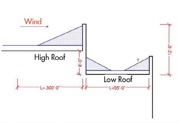
capture wall. ASCE 7-22 Equations C7.7-9 and C7.7-10 can be used to calculate hd*, the expected leeward drift height atop the lower level roof for a capture wall shorter than the height required for a full capture wall. The component of the upwind fetch due to the upper roof in ASCE 7-22 Equations C7.7-3 and C7.7-4 can then be reduced proportionally.
See Snow Loads: Guide to the Snow Load Provisions of ASCE 7-22 for example calculations of leeward drifts for roof steps in series and for full and partial height capture walls.
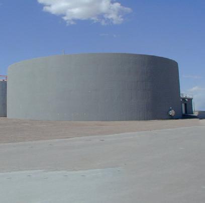
Wind Loads on Circular Bins, Silos, and Tanks
A: Do the ASCE 7-22 Section 29.4.2 wind load criteria consider the effects of an internal pressure coefficient acting on an open top or open bottom circular bin, silo, or tank?
A: While dead load is less variable than other loads, there is still some uncertainty in the actual load due to variations in unit weights and dimensions of both structural and nonstructural items. The 0.9 factor used in load combinations where dead load resists the effects of other loads is determined from a reliability analysis using a normal distribution for the dead load with a mean of 1.05D and a coefficient of variation of 0.10. For a detailed explanation of the reliability analyses used in ASCE 7, see Structural Reliability Guidance in ASCE 7-22: Principles and Methods.
Q: Do ASCE 7-22 ASD load combinations 7a and 10 assume that, during construction, only 60% of the dead load is available to resist lateral loads?
A: No. The 0.6 factor applied to the dead load in ASD load combinations 7a and 10 is necessary to achieve similar reliability between strength design and allowable stress design. For an in-depth explanation, see “Counteracting Structural Loads: Treatment in ASCE Standard 7-05” in the Journal of Structural Engineering (https://doi.org/10.1061/ (ASCE)0733-9445(2009)135:1(94))
For structures under construction, the load combinations in ASCE 37-14 (R2019): Design Loads on Structures Under Construction should be used for design. In the case of counteracting forces, the ASCE 37 ASD load combination is 0.6D+CD+(0.6W or 0.7E), where D is the portion of the permanent structure dead load in place at the stage of construction being considered and CD is the dead load of temporary structures in place at the stage of construction being considered.
Partial Capture Walls for Snow Drift
Q: What fetch length do I use for windward snow drift at the low roof parapet (wind from left to right) when the high roof parapet acts as a partial capture wall?
A: The effectiveness of the high roof parapet as a capture wall can be determined by comparing the height of the leeward drift at the roof step with the capture wall to the height of the leeward drift at the roof step if there were no
Q: Section 29.4.2 is used to check overturning stability and sliding. An internal pressure coefficient is not included in the lateral design wind force for circular bins, silos, and tanks because the internal pressure does not contribute to the overturning moment or base shear for these structures. The internal pressure coefficient is considered when determining the uplift pressure on the roofs of isolated circular bins, silos, and tanks per Section 29.4.2.2. When checking the pressure distribution around the shell of circular bins, silos, and tanks rather than overall stability, the internal pressure coefficient for the internal surface of exterior walls of isolated open-topped circular bins, silos, and tanks is determined from Equation 30.10-5. The internal pressure coefficient for closed-topped circular bins, silos, and tanks is determined from Table 26.13-1.
A: Does the ASCE 7 committee consider the skin (i.e., shell) of a circular bin, silo, and tank to be classified as components and cladding?
Q: The component and cladding wind loads provided in Section 30.10 for circular bins, silos, and tanks can be used to design the shell of the bin, silo, or tank itself as well as to design traditional components and cladding elements such as insulation attachments, telecommunication antennas, or miscellaneous architectural components that attach to the shell and/or roof. ■
This article’s information is provided for general informational purposes only and is not intended in any fashion to be a substitute for professional consultation. Information provided does not constitute a formal interpretation of the standard. Under no circumstances does ASCE/ SEI, its affiliates, officers, directors, employees, or volunteers warrant the completeness, accuracy, or relevancy of any information or advice provided herein or its usefulness for any particular purpose. ASCE/SEI, its affiliates, officers, directors, employees, and volunteers expressly disclaim any and all responsibility for any liability, loss, or damage that you may cause or incur in reliance on any information or advice provided herein.
If you have a question you want to be considered in a future issue, please send it to sei@asce.org with FAQ in the subject line. Visit asce.org/sei to learn more about ASCE/SEI Standards.
F.SEI, is the Technical Director of the Structural Engineering Institute.
Jeannette Torrents, PE, SE,
iconic STRUCTURES
Vaults, Values, and the Vernacular
Structural engineering exhibits cultural expression in the Arab World.
By Ralph Hage
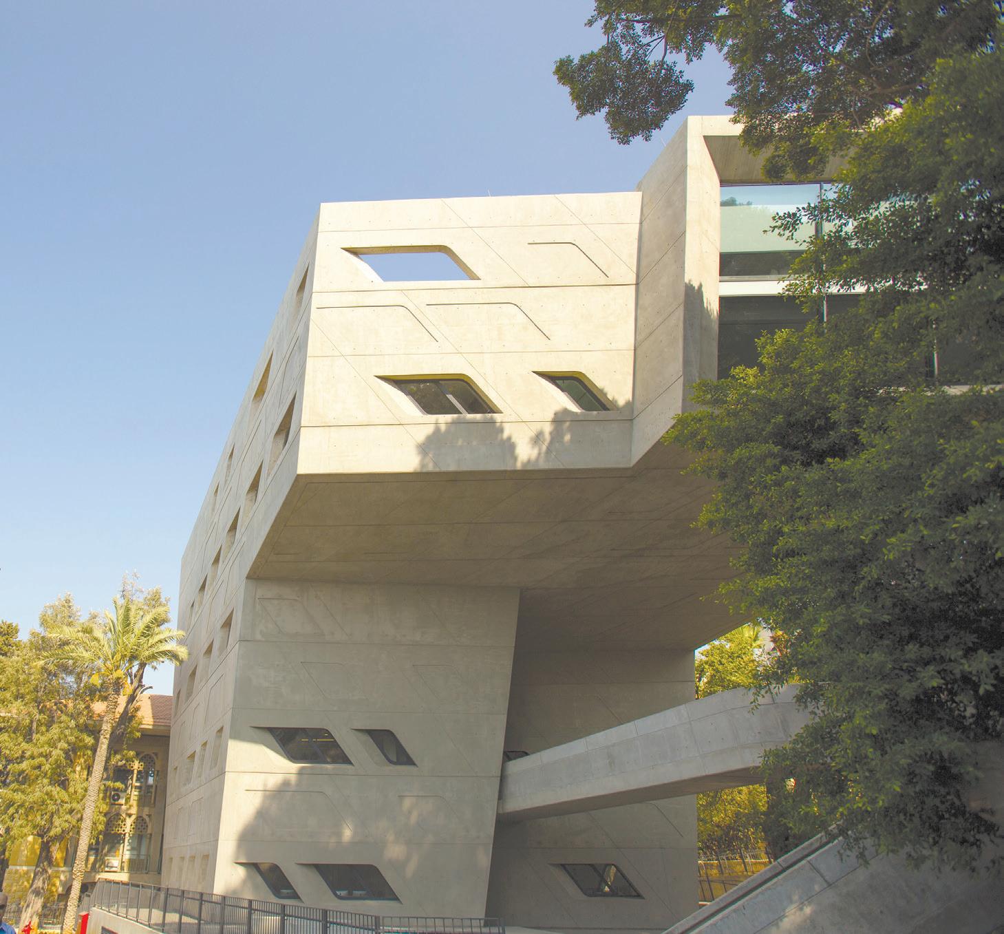
Structural engineering is often viewed as a purely technical field, focused on the precise application of material science, the optimization of forces, and the functionality of buildings. Yet, when we expand our view, we see that the practice of structural engineering has developed in various contexts, times, and cultures, influenced by local conditions, available materials, and the values of a particular society. It is a profession that requires not only technical expertise but also an open mind—an appreciation for how structures evolve to meet the unique demands of their environment and culture. By considering the cultural context in which they arise, we can better understand how these engineering solutions reflect both practicality and human creativity.
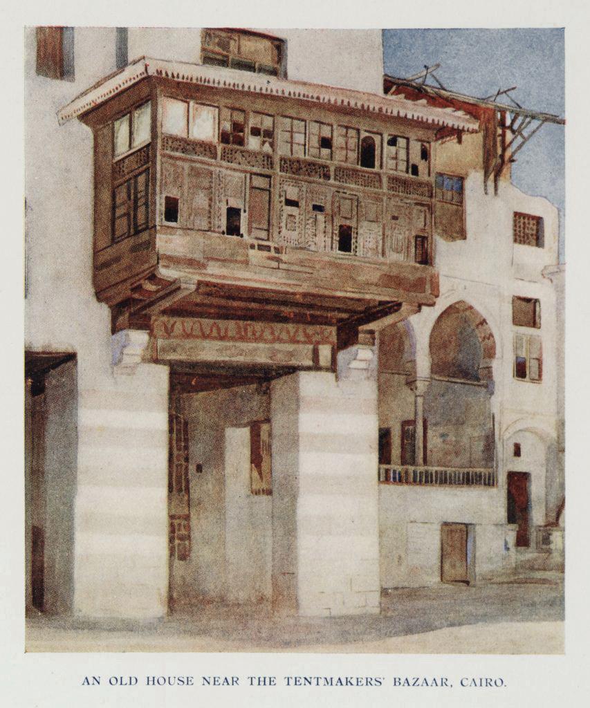
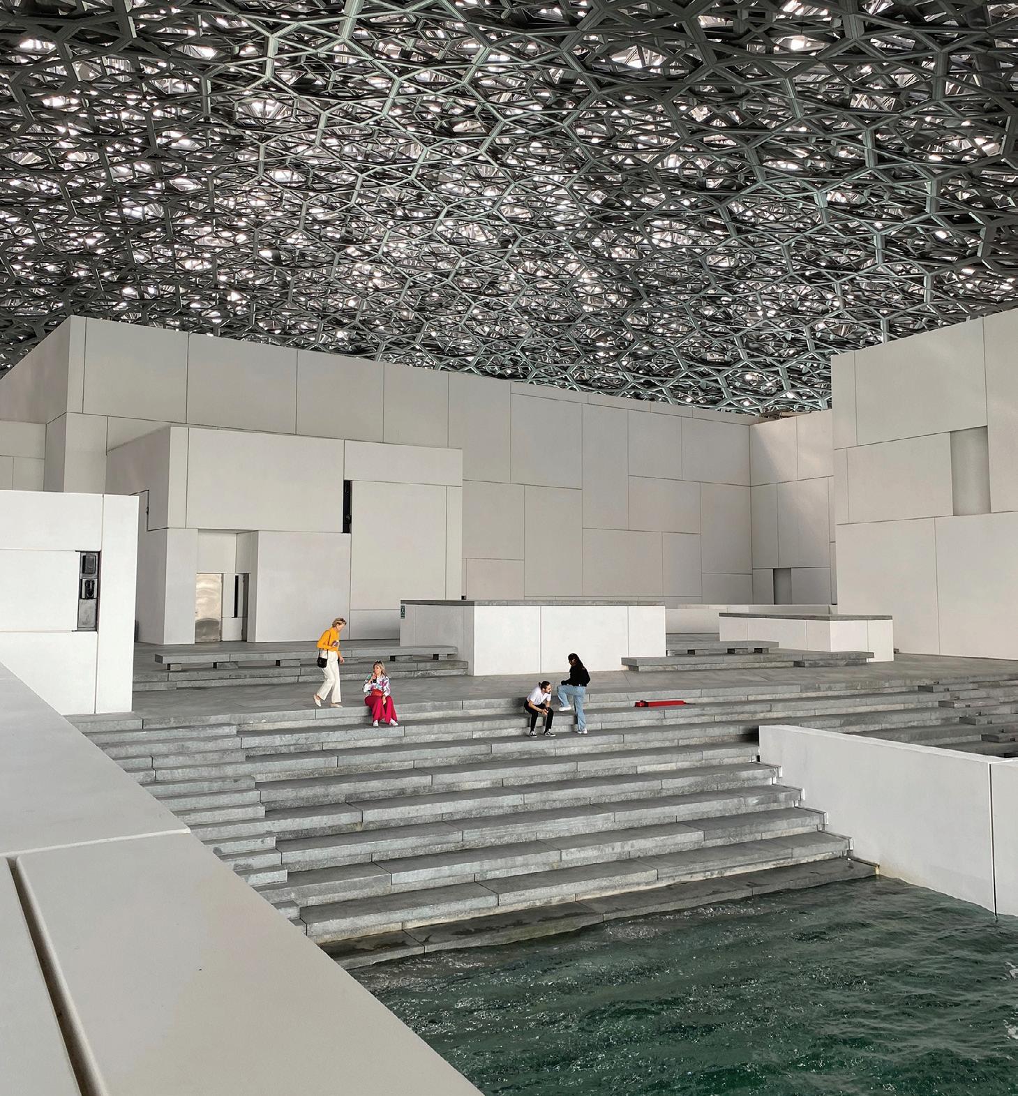
In the Arab world, structural engineering is inextricably linked to cultural identity. From the soaring domes of mosques to the intricately patterned vaults of souks and madrasas, the engineering solutions crafted over centuries in this region have served both practical and symbolic purposes. Architecture and engineering in the Arab world were not just about building shelter but about shaping spaces that reflect religious, social, and environmental values.
This article explores how structural engineering in the Arab world has evolved, beginning with early examples of ingenuity and moving through to the high-tech designs of today. By examining iconic historical structures alongside modern projects, we will see how regional engineering techniques have developed over time, meeting both the functional demands of the environment and the cultural and spiritual needs of society.
Historical Foundations—Geometry, Proportion, and Structural Ingenuity
The evolution of structural engineering in the Arab world is deeply connected to the region’s cultural and religious values, where geometry and proportion played as much of a role in shaping the built environment as did the technicalities of material science and load distribution.
Early Arab engineers demonstrated a sophisticated understanding of both the symbolism and practicality of their designs, which were always embedded in the region’s spiritual and social context.
The muqarnas vaults of the Alhambra in Spain (1238–1492 CE) stand as an exceptional example of this integration of beauty and engineering precision. Being of Arab origin, it was built by the Nasrid dynasty between 1238 and 1358 AD. This form of corbelled vaulting allowed for large, open spaces without the need for supporting columns. The muqarnas design is a structural solution that not only optimizes weight distribution across complex geometric surfaces but also carries profound spiritual symbolism representing the infinite, the divine, and the idealized order of the universe. These vaults were constructed in layers of intricately interlocking blocks, distributing weight evenly while creating a stunning visual pattern. As Robert Hillenbrand notes, they were used as both functional structures and spiritual metaphors, reflecting Islamic cosmology.
Similarly, the spiral minaret of the Great Mosque of Samarra (9th century) in Iraq demonstrates how structural engineering solutions can be both practical and symbolic. Built using corbelled brickwork,
The Temple of Bacchus in Baalbek, Lebanon, is one of the best-preserved examples of Roman monumental engineering in the Arab world. (Photo credit: Wikimedia Commons)
the minaret rises in a distinctive spiral shape, reducing the risk of collapse while providing a visually striking marker for the mosque. The spiraling form symbolizes ascension toward the heavens, reinforcing the mosque’s function as a place for spiritual connection. The design was not only a feat of engineering but a tool for expressing religious and social power, creating a structure that could be seen from great distances.
The Temple of Bacchus at Baalbek (2nd century CE), located in present-day Lebanon, stands as one of the most impressive and bestpreserved examples of Roman monumental engineering in the Arab world. Dedicated to Bacchus, the god of wine and fertility, the temple demonstrates an extraordinary command of material and structure. Its limestone columns, which are nearly 20 meters high and weigh over 60 tons each, were set with exceptional precision. The temple’s robust platform and interlocking masonry have helped it endure earthquakes and weathering for nearly two millennia. Beyond its structural mastery, the Temple of Bacchus reflects the cultural synthesis characteristic of the region: Roman in engineering and proportion yet enriched with local artistic motifs and symbolic ornamentation. The result is a structure that unites technical ingenuity with spiritual and cultural expression, illustrating how engineering served as both a scientific and cultural endeavor in the ancient world .
These examples highlight how early Arab and regional engineers combined scientific principles with cultural values. The structural innovations were designed to meet practical needs—creating large, functional spaces—but also to serve symbolic purposes, connecting the physical world to spiritual or societal ideals.
Practical Engineering Solutions—Adapting to Climate and Materials
One of the defining features of structural engineering in the Arab world is its deep connection to the environment. In many of its regions, especially in arid and desert climates, buildings had to be designed to cope with extreme temperatures, limited resources, and environmental challenges. Early engineers adapted to these constraints by developing construction
methods that were not only functional but also sustainable, ensuring that buildings would remain resilient in harsh conditions.
Thick stone and mudbrick walls were common solutions in regions with extreme temperature variations. These materials helped regulate indoor temperatures, offering insulation against the scorching heat of the day and the freezing cold of the night. The traditional courtyard design—a key feature in mosques, homes, and palaces—was a direct response to the region’s climate. Courtyards provided open spaces that facilitated natural ventilation and cooling, reducing the need for artificial cooling systems. These spaces created microclimates where the effects of the outdoor heat could be mitigated, and they also provided much-needed social areas for gathering, reflecting the cultural importance of communal spaces.
The use of mashrabiya (wooden lattice screens) also shows how engineering responded to both functional and cultural needs. These intricate, perforated designs allowed air to circulate through windows while protecting the interior from intense sunlight, offering a natural cooling effect. Beyond their utility, the mashrabiya were often symbolic, with their geometric patterns representing the balance of order and chaos, a theme central to Islamic art (Al-Asad, 1999). The screens also offered privacy in crowded urban environments, where maintaining personal space was important, especially in a society with strong social codes.
In desert regions, where mobility was often paramount, the Bedouin tent exemplifies an ingenious adaptation to both climate and lifestyle. Made from wool, animal skins, and other lightweight materials, these portable structures were easy to assemble and disassemble, offering shelter from the extreme desert heat. The flexible and lightweight design enabled nomadic groups to relocate swiftly, a functional necessity in an ever-changing environment. This temporary but resilient form of shelter showcased a sophisticated understanding of the natural world and the needs of a mobile society. These examples underscore the role of structural engineering as a practical response to environmental challenges. Yet, in each case, the design solutions were more than just functional; they were also expressions of cultural adaptation, where
Columns and arches in the Patio de los Leones, Alhambra, Granada, Andalusia, Spain. (Photo credit: Wikimedia Commons)
The distinctive spiral shape of the Great Mosque of Samarra’s minaret (shown here in Iraq circa the late 1970s) reduces the risk of collapse . (Photo credit: Wikimedia Commons)
Illustration of An Old House with a prominent Mashrabiya near the Tentmakers’ Bazaar, Cairo. (1907) (Photo credit: Wikimedia Commons)
the environment was not something to be conquered but something to be understood and integrated into the built environment.
Modern Structural Engineering—Merging Tradition with Innovation
The 20th and 21st centuries have brought about significant shifts in structural engineering in the Arab world, with contemporary architects and engineers employing modern materials and technologies to reinterpret traditional forms. These innovations allow for the creation of iconic new buildings that resonate with the cultural history of the region while addressing the modern needs of urbanization, sustainability, and functionality.
The Issam Fares Institute at the American University of Beirut (2014), designed by Zaha Hadid Architects, demonstrates the fusion of advanced structural engineering with regional architectural sensibilities. The building’s most striking feature is its cantilevered form, which extends dramatically over the site, creating an open, column-free space beneath as an allusion to traditional Lebanese courtyards. Achieving this effect required innovative engineering, combining reinforced concrete with a steel framework to balance loads and ensure stability while allowing the structure to “hover” above the landscape . The cantilever not only creates an impressive visual statement but also enhances functionality, providing shaded outdoor areas that respond to Beirut’s Mediterranean climate.
Hadid’s design also reflects her signature approach to spatial fluidity, with curving, organic forms that guide movement and frame views of the surrounding campus and city.
The building’s engineering solutions—carefully calculated load distribution, cantilever supports, and integration of natural light and ventilation—illustrate how contemporary structural techniques can respond to both environmental challenges and cultural context.
The Louvre Abu Dhabi (2017), designed by Jean Nouvel, is an excellent example of this fusion of old and new. The museum’s massive, domed roof is designed to filter light in a way that recalls traditional Islamic mashrabiya, yet it is constructed using materials such as steel and aluminum. The intricate geometric pattern of the dome is made possible by digital fabrication and computer-aided design technologies. These techniques allowed the creation of a lattice-like structure that is both light and structurally efficient, providing shade while letting light filter into the
The Issam Fares Institute in Beirut, Lebanon, was designed by Zaha Hadid Architects.
View under the Dome of Louvre Abu Dhabi. (Photo credit Wikimedia Commons)
building, mimicking the play of light and shadow in traditional Arabic architecture. This combination of traditional geometric motifs and modern engineering techniques allows the building to function as both a modern art institution and a cultural symbol.
The Qatar National Library in Doha, designed by Rem Koolhaas, provides another example of how modern engineering and architecture can draw from regional traditions. The library’s vast, open interior is supported by post-tensioned concrete and steel cable systems that allow for column-free spaces. The design creates a flexible, adaptable space that can accommodate a variety of functions. Koolhaas also incorporated elements of traditional Arab architecture, such as the central courtyard, into the design which emphasizes openness and connectivity while responding to the regional climate and social context .
These modern projects illustrate the evolving role of structural engineering in the Arab world—where new technologies and materials allow for more complex, sustainable, and efficient buildings that maintain cultural roots. Parametric design, 3D printing, and sustainable building practices have all become integral to modern construction in the region, facilitating the creation of structures that reflect the cultural and environmental needs of the Arab world while pushing the boundaries of what is technically possible.
Structural Engineering Today—Preserving Identity through Innovation
Today’s engineers in the Arab world are tasked with addressing contemporary challenges such as rapid urbanization, environmental
sustainability, and the integration of new technologies while still honoring the region’s architectural heritage. Through the use of digital tools, sustainable materials, and environmentally responsive designs, structural engineers are creating buildings that are both cutting-edge and deeply reflective of the region’s cultural and social values.
The integration of green technologies like solar panels, high-performance insulation, and water-saving features has become commonplace in the design of buildings throughout the region. Engineers are increasingly adopting passive design strategies to optimize natural light, ventilation, and cooling, reducing the reliance on energy-intensive air conditioning systems. This emphasis on sustainability ties back to the region’s long-standing respect for the environment and natural resources.
As the region continues to grow, structural engineers will play an increasingly vital role in shaping the built environment—one that not only meets the technical demands of modern life but also reflects the Arab world’s rich cultural history and commitment to innovation. ■
Full references are included in the online version of the article at STRUCTUREmag.org .
Ralph Hage is an architect and writer whose work explores the intersections of art, architecture, and cultural heritage in Lebanon and across the Arab world.
Qatar National Library is a mix of modern design with a vast open interior and traditional Arab architecture, such as the central courtyard. (Photo credit Wikimedia Commons)
historic STRUCTURES
Frisco Bridge, (Memphis Bridge) 1892
19th Century Mississippi River Bridges
By Dr. Frank Griggs, Dist. M. ASCE
In late 1884, two corporations submitted a request to Congress for authorization to build a railroad bridge across the river at Memphis, Tennessee. At the time the closest bridge across the Mississippi was the Eads Bridge at St. Louis, Missouri, and that was 400 miles north of Memphis. Ten railroad lines were already entering the city from the west and east. The lines on the easterly side of the river converging on Memphis were the Louisville and Nashville (L & N), the Southern, the Nashville, Chattanooga and St. Louis, the St. Louis and San Francisco, and the Illinois Central Railroads. Across the river the largest lines entering from the west were the Kansas City, Memphis and Birmingham, the Kansas City, Ft. Scott and Memphis, the St. Louis, Iron Mountain and Southern, and the Little Rock and Memphis Railroads. Car ferries were used to carry trains across the river. An act called the “Casey Young Bridge Bill” was passed and granted the two separate private companies, the Tennessee and Arkansas Bridge Company and the Tennessee Construction and Contracting Company, right to build a bridge. The authorization was approved February 26, 1885, with the following conditions:
• The bridge is to be built with unbroken and continuous spans (in other words no swing spans).
• The length of the channel spans (two in number) is not to be less than 550 feet.
• No span shall be less than 300 feet.
• The lowest part of the superstructure shall be no less than 65 feet above extreme high water.
• And the bridge shall not at any time substantially or materially obstruct the free navigation of the river.
Once again, the Federal Government changed the horizontal and vertical clearances required to 55 feet and 65 feet. The Eads Bridge upstream required 500 feet and 50 feet clearances. The legislation did not allow for the companies to consolidate so a new company was formed, The Kansas City, Fort Scott, and Memphis Railroad Company and charted in 1887, to construct a bridge and railroad tracks over the Mississippi River from Marion, Arkansas, to Memphis, Tennessee. The three-mile line was controlled, and its mortgage guaranteed, by the Kansas City, Fort Scott, and Memphis Railroad Company. When they went back to Congress, the clearances were once again changed. The House approved HR 2927 on May 24, 1886, with amendments of July 17, 1886. They recommended two spans of 600 feet and others at 450 feet and a vertical clearance of 65 feet and sent it the Senate where a long debate took place on April 2, 1888. Some senators wanted to make the clearance
Portal and provision for both rail and wagon traffic are shown here. No wagon traffic was allowed on the bridge when trains were crossing.
1,000 feet horizontally and up to 100 feet vertically and an official minority report of the Committee on Commerce on January 17, 1888, recommended 1,000 feet and 85 feet above extreme high water. The Mississippi River Commission had earlier recommended 1,000 feet and 75 feet clearances. The Bill, An act to authorize the construction of a bridge across the Mississippi River at Memphis, Tennessee, was finally approved on April 24, 1888 with the following requirements:
Provided, That the main channel span shall in no event be less than seven hundred feet in length, or the other spans less than six hundred feet each in length; and if the report of said officers shall be approved by the Secretary of War, the spans of said bridge shall be of the length so required. The lowest part of the superstructure of said bridge shall be at least seventy-five feet above extreme high-water mark, as understood at the point of location, and the bridge shall be at right angles to and its piers parallel with the current of the river.
George Morison was selected as Chief Engineer in 1886, and while negotiations were underway in Congress, he prepared preliminary plans based upon a site survey and borings. In February 1887 he submitted a report to the bridge company for a bridge with three 660-foot simple spans as well as a preliminary plan for a 1,300-foot cantilever span. The Act as passed also stated, “three engineer officers from the Engineers Bureau to be detailed to the duty of examining, by actual inspection, the locality where said bridge is to be built and to report what shall be the length of the main channel span and of the other spans.” The Board was split with some wanting 1000 feet and others 700 feet, but Secretary of War William Endicott wanted 770 feet. Based upon this, Morison, against his best wishes, made his easterly channel span 790 feet cantilever span with two side spans of 621 feet 6 inches and added provisions for wagons and animals. The span lengths from east to west (Memphis on right) were:
• Cantilever span………621.06 feet (cantilever arm 169. 38)
• Deck span……………338.75 feet
The 790-foot span was the longest in the United States when built. Morison made the width, center to center, of his spans 30 feet with a depth of truss over his piers 77-feet, 7 inches with the depths of his suspended spans of 56 feet, 5 ¼ inches. The truss style was a double intersection Warren. The westerly viaduct consisted of 59 feet plate girder spans with 29.5 feet braced steel bents (three masonry bents when crossing railroads) for a total length of 2,290.6 feet and followed by a wooden trestle 3,097.5 feet long on a 1.25% grade.
Preliminary work started in late 1888 but full-scale work was not authorized until January 1, 1889. The foundations were placed using pneumatic caissons with a maximum depth of 130 feet.
The superstructure was fabricated by the Union Bridge Company under Charles Macdonald and the erection by the Baird Brothers. They had a difficult time closing the cantilever span that was described thoroughly in Morison’s A REPORT, GEORGE H. NETTLETON, PRESIDENT OF THE KANSAS CITY AND MEMPHIS RAILWAY AND BRIDGE COMPANY written in 1894. Morison was in the habit of writing similar reports on the bridges he built in the last third of the 19th century.
The bridge opened for traffic on May 12, 1892. The bridge still serves today with the westerly viaduct replaced in 2017. It now has two neighboring bridges, the Memphis and Arkansas and the Harahan Bridges. Upstream is the Hernando De Soto vehicular bridge. ■
Full references are included in the online version of the article at STRUCTUREmag.org
In this site plan of the Memphis Bridge, note the long viaduct on the Arkansas (west) side of the river.
Profile of bridge and partial viaduct on Kansas side of river.
Dr. Frank Griggs, Dist.M. ASCE, specializes in the restoration of historic bridges, having restored many 19th Century cast and wrought iron bridges. He is now an Independent Consulting Engineer (fgriggsjr@verizon.net).
s k A r c h i e , O u r N e w S E G P T
Check out our updated AIpowered tool educated on the NCSEA ecosystem, including STRUCTURE’s archives.
Each new issue of STRUCTURE and its articles are posted to the website, dating back to 2012 F r e e W e b i n a r s
Watch a collection of free presentations from STRUCTURE and its partners
The Dalí Unveils Transformative Vision
The Dalí Museum, St. Petersburg, Florida, announced plans for a transformative expansion, in step with the Tampa Bay region’s growth.
Since opening in St. Petersburg in 1982, The Dalí has welcomed and inspired more than ten million visitors. Following the debut of its landmark building in 2011, the Museum generated over $1 billion in economic impact for the area, solidifying its role as a global destination for groundbreaking interdisciplinary programming, innovation and scholarship.
Rooted in Salvador Dalí’s demonstration that the world cannot be understood from a single perspective, the expansion reimagines in concrete, steel, and digital delivery what a museum can be—creating more inclusive, inspiring environments for growth, dialogue and connection.
Designing the Museum of the Future
The Beck Group, which constructed the Museum’s landmark 2011 building, has been selected to design and build the expansion. During the design of the expansion, Beck Architecture consulted with internationally recognized architect Yann Weymouth, FAIA, of PBK, architect of the Museum’s original award-winning building, to ensure continuity across the institution.
The 35,000-square-foot expansion introduces a striking new exterior, flexible gallery environments for experiential exhibitions that blend art and technology, a dedicated learning center serving K-12 students and lifelong learners and community-focused
spaces designed to support, host and animate social, corporate and cultural events.
Groundbreaking is anticipated in fall 2026. The Dalí will remain open throughout construction and plans to open its expanded spaces in 2028.
A 3D model of the proposed expansion will be on view beginning May 2, 2026, as part of The Architecture of The Dalí, a special exhibition exploring the Museum’s architectural evolution and future vision.
To learn more about the vision and future of The Dalí’s expansion and view project renderings and images, visit Expansion.TheDali. org. For more information on The Dalí, visit TheDali.org. ■
TThe Beck Group will be designing and building the expansion for the Dalí Museum in St. Petersburg, Florida.
Univ. of Maryland Team Wins PCI Design Precast
Brandon Bosaz’s and William Walker’s plan for a precast living/learning community they called Innovation Innovillage captured the top prize in the second annual PCI Design Precast contest. In the competition, college architecture students explore innovative uses of architectural precast concrete enclosure systems in structural, sustainable, and artistic ways.
Teams of two or three students present their designs in the form of elevations and 3-D BIM modeling. Students are encouraged to work with a local PCI-certified precast concrete producer to learn about the design-assist method, understand precast concrete production, and the colors and textures needed to complete the design.
“Going into it I didn’t really know a lot about precast concrete beyond parking garages,” said Bosaz. “I didn’t know that were more building types and applications we could do using precast concrete. This forced us to think outside the box and create something that traditionally I would not conceive as a total-precast structure.”
“This is what we thought we would want to see as students ourselves on a university campus if we had the option to design it,” Walker added. He credited Lloyd Kennedy of Finfrock for discussing sustainability with the team and suggesting how to implement it into the design.
Walker and Bosaz presented their winning design at the 2026 PCI Convention in March in Kansas City, Missouri.
2025 Design Precast Top Three Teams
• First: Brandon Bosaz and William Walker
• Second: Andy Huynh, Thach Pham, and Kevin Xu
• Third: Abby Heng, Bonnie Tran, and Catlinh Tran
The 2026 PCI Design Precast Competition opens June 1. ■
AISC, RCSC Release Design Guide on Structural Joints
There’s a new resource for anyone designing connections with stainless steel bolts: Design Guide 41, Structural Joints Using Stainless Steel Bolts, from the American Institute of Steel Construction (AISC) and the
Research Council on Structural Connections (RCSC).
Design Guide 41 contains information about specifying, designing, installing, and inspecting connections using stainless steel
bolts, all formatted to align with the provisions of the RCSC Specification for Structural Joints Using High-Strength Bolts. The guide reviews and provides guidance for considerations unique to stainless steel bolts, including connections between stainless steel elements as well as those between stainless and carbon steels. These recommendations expand upon existing design provisions and information in the RCSC Specification, ANSI/ AISC 370-21, and the second edition of AISC Design Guide 27, Structural Stainless Steel. The new guide covers snug-tight, pretensioned, and slip-critical bolted connections, with several useful design examples to illustrate the concepts discussed.
The joint AISC/RCSC guide was authored by some of the industry’s leading experts: Francisco Meza, PhD, principal engineer at the Steel Construction Institute (SCI); Nancy Baddoo, associate director at SCI; and Jason Provines, PE, senior research scientist at the Virginia Transportation Research Council. Design Guide 41 is available for download at aisc.org/dg. Like all digital design guides, it is free for AISC members. ■
Brandon Bosaz (left) and William Walker won first place in the 2025 PCI Design Precast competition. They presented their winning entry at the 2026 PCI Convention. Photo: PCI
Oxford University Earns Passive House Certificate
The British University of Oxford has built its new Centre for Humanities to the energy-efficient Passive House standard, as certified by the Passive House Institute. The Passive House concept drastically reduces the heat loss characteristic of buildings through walls, windows and roofs. With its five principles—1) good insulation, 2) windows with good thermal insulation and triple glazing, 3) ventilation system with heat recovery, 4) avoidance of thermal bridges, and 5) airtight building envelope—a Passive House building requires very little energy for heating and cooling. Passive House buildings can therefore do without a conventional heating system.
With its limestone and brick facade, constructed within a few weeks using prefabricated elements, the new building blends in with the characteristic buildings of the historic city of Oxford. The big difference is its high energy efficiency: the new Humanities Centre features good thermal insulation and an airtight building envelope, as well as Passive House windows and a ventilation system with heat recovery. In addition, 100 photovoltaic modules were installed on the roof of the building complex for generating renewable energy. According to the university, low-carbon concrete as well as steel with a very high recycling rate were used in the construction. Further information on the project is available in the Passive House Institute database at www. passive-house-database.org. ■
. Join 1,000+ structural engineers learning from leading experts at the NCSEA Structural Engineering Summit
October 27-30, 2026
san francisco, CALIFORNIA registration opens this spring
With its limestone and brick facade, the exterior of the new Passive House building blends in with the buildings that are characteristic of the historic city of Oxford. The new complex is highly energy-efficient and will save significant energy costs over its decades of future use. (Photo credit: Will South, Etude)
HDR-STV to Deliver Design for West Point’s Thayer Hall
HDR and STV have been selected to deliver architecture and engineering services to modernize Thayer Hall (Building #601) at the United States Military Academy (USMA) in West Point, New York. The multistory general instruction building will become the hub for the United States Military Academy’s humanities disciplines. The joint venture, contracted by the U.S. Army Corps of Engineers (USACE), will work with the Corps’ New England District.
HDR will collaborate with STV to renovate, retrofit, and modernize the facility with resilient infrastructure. HDR will lead architectural design and preservation, while STV will provide engineering services.
Thayer Hall is a key component of USMA 2035, West Point’s ambitious plan to modernize its campus facilities, infrastructure and academic
IN BRIEF
John D. Tickle Honored with Silver Antelope Award from Scouting America
Strongwell (USA), pultruder of fiber reinforced polymer (FRP) composites, announced its Chairman, John D. Tickle of Bristol, Tennessee, has been awarded the prestigious Silver Antelope Award by Scouting America.
Created in 1942, the Silver Antelope Award is a Council Service Territorylevel distinguished service award presented by the National Court of Honor. The award recognizes registered Scouters of exceptional character who have provided distinguished service to youth within their territory.
capabilities, and the centerpiece of its Academic Building Upgrade Program.
The project will deconstruct and reconstruct the multistory facility while preserving and rehabilitating key historic elements from the original 1909 structure. Once complete, Thayer Hall will feature two additional floors. The revitalized building will include general instruction classrooms, lecture halls, labs, a library, auditorium, mock courtroom, administrative offices and a variety of student and faculty support spaces. A 1955 addition will be replaced with a modern, compatible extension. The interior design will introduce daylight and support modern pedagogy, creating a more engaging and inspiring environment. The exterior will reflect West Point’s rich heritage and military Gothic architectural style. ■
detailing, and fabrication-ready modeling. The DeSimone VT practice provides a full complement of services, from due diligence and concept development through construction and installation for new construction, modernizations and ongoing maintenance. Edgett’s portfolio includes Apple Park, Google’s Bay View Campus, Shanghai Tower, and the award-winning JPMorgan Chase Headquarters at 270 Park Avenue—a 2.6 million-square-foot, fullcity block, 1388-foot supertall designed as a high-capacity vertical office building with some 90 elevators and escalators.
CPL Announces Strategic Partnership
CPL, an architecture, engineering, and planning firm, announced a strategic capital partnership with GHK Capital Partners LP, a private equity firm focused on long-term investments in growthoriented businesses.
The Silver Antelope Award is one of Scouting America’s highest honors at the territory level and is reserved for volunteers whose service has had a significant and lasting impact on youth development.
Tickle has previously been recognized for his Scouting service as a Distinguished Eagle Scout and as a recipient of the Silver Buffalo Award, the Silver Beaver Award, the Heroism Award, and membership in the W. P. Society, among other honors.
Vertical Transportation Expert Steve Edgett Joins DeSimone
DeSimone Consulting Engineering has announced that Steve Edgett has joined the firm as Senior Technical Advisor, strengthening and expanding its market-leading Vertical Transportation (VT) practice.
Recognized as one of the nation’s foremost VT experts, Edgett’s appointment reflects DeSimone’s continued investment in growing its integrated engineering capabilities across major U.S. markets, extending from structural engineering to facade and building envelope consulting, structural
This capital partnership is designed to amplify the firm’s capabilities, expand capacity, and unlock the next phase in CPL’s ambitious five-year plan. CPL’s leadership team will continue to lead the firm’s strategy and day-to-day operations.
Ardurra Group Makes Acquisition
Ardurra Group, Inc. has acquired Remington & Vernick Engineers (RVE), a water and municipal engineering company serving the Northeast. Ardurra delivers complex engineering and design services to public and private entities across the United States.
Founded in 1901, RVE is one of the oldest established engineering consulting firms in the United States, with more than 500 professionals across 14 offices. The firm provides design, planning, and construction management/inspection services across water, municipal, transportation, and other end-markets.
RVE will continue to operate from its primary office in Cherry Hill, New Jersey, along with 13 additional offices across New Jersey, Pennsylvania, Delaware, and North Carolina. Ardurra now comprises a combined team of approximately 2,600 employees across more than 120 offices nationwide.
AEC Advisors (www.aecadvisors.com), through its registered broker-dealer affiliate AEC Transaction Services LLC, was the exclusive financial advisor to RVE on this transaction. ■
John D. Tickle
Arcadis Secures 2 Project Wins in LA Worth $18 Million
Arcadis has been selected by the City of Los Angeles to support two major infrastructure programs in the city. The Los Angeles Convention Center (LACC) Modernization and Expansion program, and the Department of Public Works Bureau of Engineering’s Clean Water Program are together valued at more than $18 million, and will support economic vitality, climate resilience and improved quality of life for Angelenos.
For the LACC Modernization and Expansion project, Arcadis will provide project and construction management support services for the $2.5 billion project. This phased design-build initiative will elevate the LACC to one of the largest convention centers in the United States.
Highlights of the project include:
• 190,000 sq. ft. of additional exhibit hall space, connecting the West and South Halls above Pico Boulevard for a total of 750,000 sq. ft. of flexible, contiguous event space.
• 55,000 sq. ft. of new meeting space.
• 95,000 sq. ft. of new external event space.
CONCRETE guide
ENERCALC, LLC
Phone: 800-424-2252
Email: info@enercalc.com
Web: enercalc.com
Product: ENERCALC SEL
Description: Save hours on every steel design with ENERCALC – now with FEM capabilities. Beams, columns, two dimensional frames, force distribution in bolt groups and more. The clear, simple user interface makes it fast & easy to setup, confirm & “what-if” your designs. Member optimization improves your efficiency and saves time!
RISA Tech
Phone: 949-951-5815
Email: info@risa.com
Web: risa.com
Product: ADAPT-Builder
Description: ADAPT-Builder is powerful and easy-to-use 3D finite element software for multistory reinforced concrete and posttensioned buildings and structures. Builder delivers comprehensive workflows for complete analysis and design. Combine gravity, lateral and post-tensioning actions for efficient, complete, and accurate design. Integrate with various BIM software for seamless project deliverables.
Additionally, Arcadis will support the City of Los Angeles Department of Public Works Bureau of Engineering (BOE) through the Clean Water Program, a $7.5 million, five-year contract encompassing three key stormwater initiatives:
• Stormwater Capture Parks Program: Stormwater capture in nine San Fernando Valley parks to replenish groundwater, alleviate flooding, and improve water quality.
• Safe, Clean Water Program: Over 120 projects countywide, including marquee initiatives like Hollenbeck Park Lake Rehabilitation, targeting stormwater capture, infrastructure modernization, and climate resilience.
• National Flood Insurance Program: Floodplain management to meet and exceed FEMA standards, helping cities mitigate flooding and lower insurance rates.
Arcadis delivers data-driven sustainable design, engineering, and consultancy solutions for natural and built assets, operating in 30 countries around the world ■
LeJeune Bolt Company
Phone: 800-872-2658
Email: sales@lejeunebolt.com
Web: www.tightenright.com
Product: TNA® Torque + Angle Fastening System
Description: TNA® is the only fastening system that delivers both a quantifiable Snug Tight condition – ensuring every bolt in a connection meets a minimum requirement for tension – and the precise required angle for the perfect final pretension. No other system or method can match the TNA® Torque + Angle Fastening System for producing the highest level of accuracy and reliability in both the snug and final tensioning processes. Our TNA® Bolts meet the requirements of ASTM F3148 and are 100% Melt & Manufacture in the U.S. The Combined Method (Torque + Angle) is an approved RCSC installation method.
ASDIP Structural Software
Phone: 407-284-9202
Email: support@asdipsoft.com
Web: www.asdipsoft.com
Product: ASDIP Concrete
Description: Advanced software that performs the structural design of concrete members such as biaxial columns, multi-span continuous beams, shear walls, one-way slabs, two-way slabs, concrete and masonry out-of-plane bearing walls.
CASE in Point
Professional Development and Education Update
Online Program: Managing Small Projects Successfully
April 14 & 16, 2026 | June 9 & 11, 2026
Live Online | 8 PDHs
ACEC will offer Managing Small Projects Successfully: How to Prevent Small Projects from Becoming Big Problems as a live online program in April and June 2026.
The course is designed for project managers and firm principals and focuses on management and risk considerations specific to smaller projects. While small projects often represent a significant portion of firm revenue, they can present disproportionate risk and administrative challenges if not managed carefully.
The program is structured as four two-hour sessions delivered over two days, for a total of eight hours of instruction. Topics include:
• Planning and budgeting for small projects
• Contract considerations and risk control
• Scope management and schedule tracking
• Managing multiple concurrent small projects
• Project performance evaluation and financial tracking
The April cohort will be held April 14 and 16, 2026.
The June cohort will be held June 9 and 11, 2026.
Participants who complete the program may earn up to 8 PDHs.
The program is delivered in partnership with PSMJ Resources and is open to ACEC members and nonmembers.
CASE
TRisk in Design-Build and Collaborative Delivery
June 3, 2026 | 1:00-2:30 p.m. ET
Online Education | 1.5 PDHs Available
Risk Management in the Age of Collaboration: Design-Build, IPD, and Emerging Technologies on June 3 from 1:00 to 2:30 PM ET as part of its online education series.
The 90-minute session will examine how risk allocation and responsibility shift under design-build and other collaborative delivery models. Topics will include common breakdown points in integrated project environments, contract considerations, coordination challenges.
The program will be led by Karen Erger of Lockton, a risk management and insurance advisor to engineering firms. A structural engineering case study panelist will participate to provide perspective from firm experience.
The session is intended for structural engineering firm principals, project managers, risk managers, and firms pursuing or currently engaged in design-build projects.
Participants who attend the full program are eligible to receive 1.5 PDHs.
Registration and additional details are available through ACEC’s online education page.
Toolkit Committee Publishes Two New Tools
he CASE Toolkit Committee has released two new resources for structural engineering firms. The publications expand the CASE library of practice and business management tools available through the ACEC bookstore.
CASE Tool 2-10: Stress Management provides guidance for recognizing and addressing stress in engineering practices. The publication outlines common workplace stressors including schedule disruptions, deadlines, overtime, and interpersonal conflict, and offers strategies to mitigate their impact. It also includes a work-habit assessment and a structured stress management plan to help individuals identify inefficient habits and implement practical steps to improve productivity and well-being.
CASE Tool 9-3: Design Criteria lays the groundwork for transparent communication and mutual understanding between the engineering team and the client. By clearly defining the project’s scope, objectives, and specific requirements, the design criteria document helps to align client expectations with engineering capabilities. This Tool can work in parallel with CASE Tool 3-4 Project Work Plan, serving as Section 5.1 of the Work Plan. The bookstore is accessible through the ACEC website (www.acec.org) under Resources, then Contracts and Publications.
Engineering Excellence Awards
ACEC recently announced the Top 24 winners of the 2026 Engineering Excellence Awards, recognizing projects from across the country for engineering achievement and innovation. The list includes eight Grand Award recipients and sixteen Honor Award recipients representing a range of infrastructure, transportation, environmental, and building projects.
From this group, ACEC will select the Grand Conceptor Award, the program’s highest honor. The overall winner will be announced during the Engineering Excellence Awards Gala at the 2026 ACEC Annual Convention and Legislative Summit in Washington, D.C.
News of the Coalition of American Structural Engineers
ACEC’s Technology Committee Releases Two New Resources
ACEC’s Technology Committee recently released two new resources designed to help engineering firms evaluate and manage the integration of artificial intelligence and digital technologies into their operations.
Why and How?—A Primer on AI Integration for Engineering Firms
This document provides an overview of key considerations for firms exploring the use of artificial intelligence. The document outlines different types of AI technologies and their applications, examines potential benefits of AI integration for engineering firms, and discusses challenges associated with adoption along with strategies to address them.
The primer also reviews change-management considerations related to AI implementation and highlights governance practices
firms may consider when deploying AI tools.
Data + AI Readiness Tool
The committee also released an interactive Data + AI Readiness Tool, which allows firms to evaluate their current technology readiness using an eight-pillar assessment framework. After completing the assessment, users receive immediate results and high-level guidance. The tool also allows users to print and save their results to track progress over time, share the assessment with multiple stakeholders within an organization, and compare responses across teams to develop a broader understanding of the firm’s technology maturity. Firms may also choose to share results anonymously to help inform future ACEC resources based on member needs.
Both resources are available on ACEC’s Technology Resources page: https://www.acec.org/resources/technology/.
2026 ACEC Convention and Legislative Summit Scheduled for May 3–6
AACEC has scheduled its 2026 Annual Convention and Legislative Summit for May 3–6 in Washington, D.C.
The meeting will include legislative briefings, meetings with Members of Congress and staff, and discussions related to federal infrastructure programs, licensure policy, and building safety. Programming is organized from a multi-discipline perspective and is part of ACEC’s annual advocacy engagement.
CASE will convene its structural engineering roundtable during the Convention. Additional agenda details are expected to be released as the event approaches. More information is available here: https://convention.acec.org/
Winter 2026 Market Intelligence Brief: Health Care & Science + Technology
ACEC released its Winter 2026 Market Intelligence Brief: Health Care & Science+Technology in February. The publication provides a snapshot of current conditions and emerging trends across health care, biotechnology, pharmaceuticals, medical technology, and related research sectors.
The brief reports that the U.S. health care market is valued at approximately $70 billion and is expected to grow at an annual rate of 3–4 percent over the next five years. It highlights several trends influencing the sector, including increased investment in artificial intelligence, financial pressures affecting rural hospitals, an oversupply correction in the life science laboratory market, tariff-related uncertainty affecting
medical equipment supply chains, and continued demand for medical office buildings.
Additional sections examine demographic trends affecting health care facilities, including the growth of the population aged 65 and older and the resulting demand for senior housing, outpatient care, and specialized medical infrastructure. The brief also summarizes recent federal policy developments related to health care funding and rural health initiatives.
ACEC members can access the full Market Intelligence Brief at https://www.acec.org/resource/health-care-sciencetechnologymarket-intelligence-brief-winter-2026/.
Structural Engineering Firm Leaders Gather for NCSEA’s Second Annual Executive Retreat
Structural engineering firm leaders from across the country gathered on Amelia Island, Florida, on March 18–20, 2026, for the second annual Structural Engineering Executive Retreat hosted by the National Council of Structural Engineers Associations (NCSEA). The three-day event brought together approximately 70 firm leaders and guests for focused discussions on leadership, business strategy, and the future of the structural engineering profession.
Building on the success of the inaugural retreat in 2025, the 2026 program brought together executives, principals, and emerging leaders for a highly interactive experience centered on leadership development, firm strategy, and the evolving business landscape facing structural engineering practices. The retreat blended expert presentations with facilitated discussions and peer-to-peer exchanges, creating an environment where participants could openly share challenges and explore practical strategies for growth and resilience.
The event featured a distinguished lineup of speakers from both within and outside the profession. Presenters included Ron Klemencic, Chairman and CEO of Magnusson Klemencic Associates; Bryce Gill, economist and national speaker with First Trust; Winslow Johnson, Senior Vice President of Talent and Organizational Development at STV; Dean West, Founder and President of Association Laboratory, Inc.; Michael Gryniuk, Founder and Principal of CORA Structural; and Stacy Bartoletti, CEO and Chair of the Board of Degenkolb Engineers. Together, these leaders shared insights on topics ranging from economic trends and firm leadership to talent development and long-term strategy.
Highlights of the agenda included a “State of the Structural Engineering Profession” briefing that examined market conditions and industry trends based on NCSEA research and benchmarking studies, as well as collaborative sessions on leadership, risk management, and strategic planning. Attendees also participated in roundtable discussions designed to foster candid conversations about the challenges and opportunities facing structural engineering firms today.
Beyond the formal sessions, the retreat emphasized relationship-building among peers. Networking breakfasts, a welcome reception, and smallgroup discussions gave participants the opportunity to connect with colleagues from across the country and exchange ideas in a relaxed setting. The intentionally small, discussion-driven format allowed attendees to engage deeply with speakers and one another while building lasting professional connections.
“The Executive Retreat was created to give firm leaders a rare opportunity to step back, reflect, and engage in meaningful conversations about the future of their businesses and the structural engineering profession,” said NCSEA Executive Director and CEO Al Spada. “The energy, insights, and collaboration that emerged from this year’s gathering demonstrate the tremendous value of bringing leaders together in this focused environment.”
As NCSEA continues to expand programming for firm leadership and business practice development, the Structural Engineering Executive Retreat is expected to remain a cornerstone event for senior leaders looking for ideas to strengthen their firms.
TheYoung Members Group of the Structural Engineers Association of Colorado (SEAC) recently wrapped up another festive and highly anticipated Gingerbread Bridge Competition, bringing together professionals and students for a fun, hands-on engineering challenge. Using gingerbread, icing, and candy as their primary building materials, participants tested their creativity, structural intuition, and problem-solving skills in a spirited display of edible engineering.
Awards recognized excellence across multiple categories. In addition to honoring the strongest bridge based on strength-to-weight ratio, judges presented an Architectural Design Award, selected by three Denver-based architects, as well as the ever-popular People’s Choice Award. This year’s winning bridge in the structural design category delivered an impressive performance, supporting an astonishing 554 pounds.
Beyond the competition itself, the event provided a relaxed and welcoming environment for emerging engineers to meet peers, connect with mentors, and inspire the next generation of structural professionals. The Gingerbread Bridge Competition continues to be a highlight of the SEAC YMG calendar, serving as a reminder that engineering can be both educational and enjoyable (especially when a little sugar is involved).
The SEAC Young Members Group looks forward to even more creative designs and recordbreaking performances next year.
Attendees of the NCSEA Executive Retreat mingle during a reception ahead of two days of focused discussions on the future of structural engineering.
When Fire Meets Structure: Webinar Series Explores Design for Wildfire Resilience
Wildfires are no longer confined to remote landscapes — they are increasingly threatening communities and the structures within them. In response, NCSEA and the Structural Engineers Association of California have launched a six-part webinar series focused on structural engineering strategies for urban wildfire mitigation.
The series explores how buildings perform during wildfire events and what engineers can do to improve resilience. Drawing on research, field reconnaissance, and real-world design experience, the sessions address topics such as fire-resistant design strategies, post-fire foundation assessments, and the performance of structural materials including mass timber and steel exposed to fire.
The series began in March and continues through April, with all sessions available on demand once released. Engineers may register for the full series at any time and access the complete set of presentations.
Each webinar provides 1 PDH, with 6 PDHs available for those completing the full series. Registration is available at www.ncsea.com/education-events/webinar-series.
NCSEA Releases Updated 2025 Benchmarking Study Results
Results from NCSEA’s 2025 Benchmarking Studies are now available, providing structural engineering firms with updated insights into compensation, benefits, and workplace trends across the profession.
The benchmarking program includes two complementary resources: the NCSEA Compensation and Benefits Study and the SE3 (Structural Engineering Engagement and Equity) Survey. The Compensation and Benefits Study focuses on firm-reported data such as salary ranges, benefits packages, and workplace policies, while the SE3 Survey
Upcoming Webinars
captures employee perspectives on engagement, career development, and workplace culture.
Subscribers receive full access to results from both the 2024 and 2025 studies, allowing firms to compare trends and benchmark their practices against peers across the industry.
Firms that have not yet contributed data may still participate by submitting their information through April 1.
Learn more at www.ncsea.com/business-practices/ benchmarking-studies/.
April 21 On the Fire Line: Structures Pushed to the Extreme in the Wildland-Urban Interface
CE Credits: 1.0
April 28 Fire Engineering of Steel Structures
CE Credits: 1.0
April 30 Navigating the Unique Challenges of Succession Planning and Ownership Transition
CE Credits: 1.0
May 12 Wind Fundamentals: Understanding the “Why” Behind ASCE 7 Wind Provisions
CE Credits: 1.25
May 14 Non-Building Structures: Seattle City Light Denny Substation
CE Credits: 1.0
May 26 Structural Assessments of In-Situ Wood Members: Best Practices for Determining Allowable Design Stresses in Existing Structures
CE Credits: 1.0
SEI Update
Nominations Open for 2027 SEI Board of Governors
SEI is accepting nominations through April 15 for the 2027 SEI Board of Governors. Two positions are open for terms beginning October 1, 2026: SEI President Elect and Governor: Technical Community. These volunteer leadership roles help guide SEI’s strategic direction and support the Institute’s governance and professional initiatives.
Candidates must be SEI members in good
standing since June 30, 2025. Nominees for President Elect must be licensed structural engineers and have completed at least four years of service as an SEI Governor. Required materials include a Letter of Intent to Serve with a brief goals statement, a professional photo, biographical statement, and résumé or CV.
Nominations should be submitted by April 15 to sei@asce.org.
ASCE Announces 2026 Structural Award Recipients
ASCE has announced the 2026 Structural Engineering Paper and Achievement Award recipients, which will be presented at Structures Congress 2026. These society level structural awards recognize leading contributions to research, innovation, and professional practice within the structural engineering community.
Paper Awards
Moisseiff Award
• Xiaohu Cheng, R.Eng., S.E., G.E., M.ASCE
• Ming Xu, Ph.D., M.ASCE
• Chuan He
Raymond C. Reese Research Prize
• Sunyong Kim, Ph.D., M.ASCE
• Yanzhi Yang, Ph.D.
• Dan M. Frangopol, Sc.D., P.E., NAE, F.EMI, F.SEI, Dist.M.ASCE
Achievement Awards
Shortridge Hardesty Award
• Perry S. Green, Ph.D., P.E., F.SEI, F.ASCE
George Winter Award
• Anil Agrawal, Ph.D., P.E., F.SEI, Dist.M.ASCE
T. Y. Lin Award
• Sanghee Kim, Ph.D., M.ASCE
• Thomas H K Kang, P.E., M.ASCE
• Donghyuk Jung, Ph.D.
• Byung Un Kwon
• Dong Joo Lee
Ernest E. Howard Award
• Andrew S. Whittaker, Ph.D., P.E., S.E., NAE, F.SEI, Dist.M.ASCE
Stephen D. Bechtel Jr. Energy Award
• Brian M. McDonald, Ph.D., P.E., S.E., F.SEI, F.ASCE
SEI Forms New Committee on Seismic Bridge Design
SEI has established a new technical committee, Seismic Design and Performance of Bridges, to continue and expand the work previously led by the Transportation Research Board’s AKB50 Committee. The committee will support the bridge engineering community by examining critical seismic design issues for bridge owners and practitioners, including approaches to seismic risk mitigation that extend beyond traditional life safety objectives. Its scope includes advancing performance based seismic design methods and shaping the state of research and practice in seismic bridge engineering.
Performance-Based Design Webinar Series Continues With PBWD Session
The next session in SEI’s Performance Based Design Webinar Series, Exploring Performance Based Wind Design (PBWD), will be held on April 23, 2026. Presented by Russell Larsen, P.E., S.E., and Jon Galsworthy, Ph.D., P.E., the webinar introduces key concepts from the SEI Prestandard for PBWD, including performance objectives, wind demand characterization, modeling and analysis procedures, and acceptance criteria for Main Wind Force-Resisting Systems. The session will also review a case study of a building in Austin, Texas designed and constructed using PBWD methodologies. Register at: https://mylearning.asce.org/ diweb/catalog/item/eid/328064030.
News of the Structural Engineering Institute of ASCE
Chapter Spotlight: 2025 Graduate Student Chapter of the Year - FIU
The SEI Graduate Student Chapter at Florida International University was named the 2025 SEI Graduate Student Chapter of the Year, recognizing a period of expanded programming and strong student engagement supported by an SEI Futures Fund Small Grant. This year, the chapter hosted an international lecture on digital twinning, collaborated with industry partners through a multidisciplinary roundtable, and led hands on STEM outreach at the Coral Reef Library for local high school students. FIU students were also active at the 2025 Structures Congress in Phoenix, presenting research with support from SEI Travel Scholarships. The chapter continues to build momentum as it prepares for the 2026 Structures Congress.
SE 2050 Releases 2025 Annual Report
The SE 2050 Commitment Program has published its 2025 Annual Report, now available for free download at www.se2050.org. Entering its fifth year, the program reports 172 signatory firms, 392 Embodied Carbon Action Plans (ECAPs), and 1,584 projects submitted to the SE 2050 database—reflecting steady growth in participation and reporting across the structural engineering profession.
The report also highlights the 2025 SE 2050 Recognition Program Awardees:
• Best in Education: Walter P Moore
• Best in Reporting: SmithGroup
• Best in Reduction: DLR Group
• Best in Advocacy: KPFF
• Best Newcomer: Lionakis
Representatives from the recognized firms will share insights and lessons learned during the second SE 2050 Annual Signatory Summit on April 29 in Boston, held in conjunction with Structures Congress. Register for the Summit at www.structurescongress.org.
ASCE AMPLIFY Adds New Structural Engineering Content
ASCE has expanded the Structural Engineering content available on ASCE AMPLIFY. Newly added titles include ASCE/SEI 7623, 7423, 3714 (R2019), and 5911, along with the ASCE 722 Guides for Wind Loads and Snow Loads.
AMPLIFY provides one click Provisions–Commentary linking, redlining between editions, real time incorporation of supplements and errata, multi level search tools, and integrated features for annotations and bookmarks. Subscribers also gain access to multiple editions within each collection to support continuity across code cycles. Learn more at https://amplify.asce.org.
2026 ASCE OPAL Awards Honor SEI Fellow
ASCE has announced the 2026 recipients of its Outstanding Projects and Leadership (OPAL) awards, which recognize lifetime achievement in construction, design, education, government, and management. John D. Hooper, P.E., S.E., NAC, NAE, F.SEI has been selected for the Leadership in Design award in recognition of his careerlong contributions to seismic design, structural resilience, and the advancement of performance based practice.
Hooper’s work spans more than 500 projects across diverse markets, including major high-rise, stadium, and aviation facilities. His leadership has significantly influenced modern seismic design approaches and contributed to the development of resilient structures in regions of high seismic risk.
ASCE will recognize the 2026 OPAL honorees at the OPAL Gala on October 15, 2026, in Reston, Virginia.
Futures Fund Supports $300,000 in Strategic Initiatives for FY26
The SEI Futures Fund has committed more than $300,000 to strategic initiatives in FY26, supported by generous contributions from individual SEI members, corporate donors, and a year-end gift match by Thornton Tomasetti. These investments strengthen programs that develop emerging leaders, advance sustainability, expand educational resources, and support chapter and committee activities across the Institute. Current priorities include:
• Scholarships and grants for students and young professionals
• Toward Zero Carbon initiatives
• Educational resources such as the ASCE/SEI 7 Primer
• Chapter programming, leadership development, and engagement activities
A full donor list is available at https://go.asce.org/seifuturesfund.
structural FORUM
So, You Want to Start Your Own Firm
In this inaugural article of a three-part series, the author explores the first step in deciding whether to start your own structural engineering business.
By John Dal Pino
At some point in your career, conditions may dictate that you want to or perhaps need to start your own firm. But like many decisions you may make on an emotional rather than rational basis, you may later regret, to one degree or another, that you had not first asked a trusted advisor for their wisdom or “read the fine print.” As you will learn, there are probably more things that you don’t know about running a business than you do know, at least at the start.
After 40 plus years in the industry, from newbie engineer to senior principal, I have seen a lot and interacted with every position in a company from the Board of Directors, to the C-Suite, to Finance and Accounting, to Marketing, to Profit Sharing and 401(k) trustees and to last, but not least, the rank and file engineers and drafters. I personally held several of these positions, but in terms of day-to-day responsibilities, I mostly concentrated on structural engineering, project management, and trying to keep our clients happy enough so that they would hire us again without asking competing firms for alternative proposals. Having repeat clients is the secret sauce to success if you don’t know! The rest of running the business was by others. I trusted that they would do their jobs, and I assume they trusted that I would do mine.
I wrote this article series to provide helpful information that I learned before and since I started my own firm. Like those disclaimers you may hear on radio shows, the information I provide herein is for general information only and is not intended to be specific to any individual or situation. I am only a licensed structural engineer, who happens to have an MBA degree. If you need proper advice, please consult an attorney or tax professional.
Setting the Stage
Your mindset ought to be that you are starting a company that just happens to provide engineering services. You are not just doing what you did before, engineering design mostly, and getting paid for it. If you can “flip the script” so to speak, congratulations, you are going to be a small business owner!
The key to small business success is earning revenue to pay the bills while doing something you enjoy. And the key to revenue generation is marketing. The four Ps of marketing—Product, Price, Place, and Promotion—run throughout this article series and ought to always be top of mind.
It is safe to say that most engineers, with several years of experience, are likely to have the basic technical knowledge to do their own projects. But fundamental to business success, which is the goal here, is the ability to generate sufficient and consistent revenue relative to costs on a long-term basis.
One of the first questions to ask yourself is, “Does a market exist for my “product” i.e. services?”
This is the most important question that needs to be answered when deciding whether to start your own company. It is safe to say that most engineers, with several years of experience, are likely to have the basic technical knowledge to do their own projects. But fundamental to business success, which is the goal here, is the ability to generate sufficient and consistent revenue relative to costs on a long-term basis.
Despite stories to the contrary, there is no shortage of engineers willing to take on more work. Multiple engineering firms will chase every advertised project even when they are busy. That is just the survival mechanism in human nature. If you decide to go out on your own and enter the marketplace, you will be facing competition from established firms who are not going to willingly or happily cede business to you. So, before you take the plunge, ask yourself if your offering will:
a. Address an underserved existing market, measured either by project work type or geographic location.
b. Provide a completely new service that creates its own market, with little to no existing or near-future competition from established firms.
c. Leverage a significant number of your client contacts that you are confident will follow you to your new firm.
d. Provide superior characteristics to those of existing firms in terms of knowledge, cost, quality, client care, etc.
If you can answer yes to one of these questions, you have a fighting chance. However, as many in the restaurant industry unfortunately find out after a year or two in business, new offerings of an equal nature in an already crowded market face difficult and often insurmountable challenges.
Starting-Up
In 1993, during Hilary Clinton’s efforts to promote her healthcare reform plan (commonly referred to as “Hilary Care”), when confronted with concerns that the mandated employer-provided health insurance would force small businesses into bankruptcy, she replied: “I can’t go out and save every undercapitalized entrepreneur in America.”
That quote always comes to mind when I think about new ventures. Capitalism can be cruel, particularly to an undercapitalized business, which is basically every new business. Unless you don’t need to be responsible for others, or you have a safety net to catch you should you fall, you will need a sufficient capital base at start-up to weather the known and unknown storms that lie ahead.
There is also a lot of uncertainty. A statement by Donald Rumsfeld, Secretary of Defense, during a 2002 Pentagon press briefing helps me put business risk into a useful analytical framework. Rumsfeld said “because as we know, there are known knowns; there are things we know we know. We also know there are known unknowns; that is to say we know there are some things we do not know. But there are also unknown unknowns—the ones we don’t know we don’t know. And if one looks throughout the history of our country and other free countries, it is the latter category that tend to be the difficult ones.”
The “known knowns” and “known unknown” storms will determine the amount of capital that you will need at the outset. We will get to the “unknown unknowns” later.
Unless you don’t need to be responsible for others, or you have a safety net to catch you should you fall, you will need a sufficient capital base at start-up to weather the known and unknown storms that lie ahead.
Known Knowns
Branding and Promotion
You need to come up with a company name (for the company legal filing) and a logo for your letterhead, calculation pads, title block, and business card. If you aren’t the creative type, get some professional help with these.
One of my first clients said to me “John, make sure your invoicing looks professional.” I took that to heart. You really need to set up a separate email account, with a corporate domain name, for the company. If I see abc@gmail.com, I think amateur or working from home. Also consider using a post office box as your mailing address. Using your home address for mailing seems less than professional and also tells the world where you live!
Do you need a website? Do you want one? Can you afford one? Can you afford not to have one? The costs can vary wildly depending on who you hire, the complexity of the site, and the upkeep. What do you intend to show your clients? You probably can’t use photos of work you did at your old firm even if you give them credit.
Insurance
Most clients, or at least the ones you probably want to work for, will require that you have professional liability (errors and omissions) insurance and general liability insurance. The cost will likely be in the $5,000 to $10,000 range per year for even the smallest firms. Some companies will let you pay on a monthly basis after an initial down-payment which will help out.
Legal
You will need to establish your operation legally in the state or states where you will operate. Each state has different laws. Some states allow engineers to operate as limited liability companies (LLC), while others, such as California, require engineers to be sole-proprietors, partnerships, or some type of corporation, typically either an S or C.
You will want to select the corporate structure that shields your personal (non-corporate assets) as much as possible and limits your personal financial liability beyond what insurance will cover. Therefore, it is crucial that you do some homework and select the one that works best for you. A good business lawyer will be of immense help by describing the various pros and cons to help you make the best decision.
A new business will require many forms to file, articles of incorporation to draft and file, etc. I was lucky to live across the street from a friendly lawyer who helped me. Otherwise expect to incur some costs.
Software and Hardware
Your former employer provided you with all of the software and equipment you needed. Now you have to purchase them. You will probably need structural analysis software or licenses (RISA 2-D or 3-D, ETABS, SAP, Ram, etc.), CAD/Revit software or licenses, and word processing software (Bluebeam, Microsoft Office). Don’t forget computers and printers. It all adds up. You may have to make do with less than the optimum amount for a while. It all depends on your available start-up capital and cash flow and what you are working on.
Miscellaneous
All of the other employee costs that used to pass-through to your employer are now yours to pay for. You will spend money on marketing lunches, advertising, attendance at webinars and conferences, professional licensing in several states, professional society membership (AISC, ACEC/SEI, NCSEA, etc.), codes and standards, books, reference material, etc. You might need to delay some of these costs for a while until you have revenue flowing in.
Known Unknowns
Part 3 of this series will cover billing for the work. But the major issue with starting up a new firm is that you don’t have any billings!
Cash Flow
The first incoming revenue will likely be several months after you start up. You first need to win projects (hopefully you have some work opportunities lined up before you start on your own), start doing the work, bill for the work and get paid, promptly if possible. This could easily take three to six months or more to reach a significant volume. Even once you are established, keeping track of billings and collecting monies promptly will be critical, no more so than when you are starting
Slow Work Periods
Can you survive the inevitable slow periods of several months, when your clients may be away or distracted by other more pressing demands than providing input to you?
Bad Debt
Hopefully you get paid for all of your work, but sometimes you don’t. You need to account for this possibility.
Unknown Unknowns
These are impossible to anticipate because, by definition, they are unknown events that you have never considered. I suppose you could sit down and dream up every possible doomsday scenario that has ever occurred throughout history and try to plan for them. That would probably put you in the 1% crowd.
The most recent example is COVID-19. You might have thought about a public health emergency, but who thought it possible that we would be ordered to stay home for a few weeks (long shot #1) and that work from home order would extend for a year or longer, depending on where you live (long shot #2)? If you were just starting out in early 2020, you would have more likely than not suffered mightily. Well-established firms, with more resources, did. Many firms went out of business due to delayed projects, lack of customers and uncertainty about the future. But the questions to ponder are “can I survive as a start-up,” “how resilient is my firm,” and “what should I be doing to prepare?”
Conclusion
The running of the business should be top of mind every day, with the engineering part second. If you have always been “just an engineer,” this is not natural; but it is what you are signing up for. Plan on many late nights taking care of everything that didn’t get done during the day. You must also honestly evaluate whether you have the wherewithal to run a business and whether you can offer a service that will be able to generate sufficient revenue for the long haul. You will be facing many risks that could end your endeavor in its infancy if you don’t understand and address them. There is no guarantee that you will be successful. But if you are up for the challenge, congratulations! Stay tuned for Part 2 in the June issue of STRUCTURE .■
John Dal Pino, SE, is a Principal with Claremont Engineers Inc., Oakland, California and the Chair of the STRUCTURE Editorial Board.
structural FORUM
Challenges & Struggles to Be Resolved in the Consulting Engineering Practice
Engineers who embark on the practice of consulting will experience frustrations and rewards.
By Neil Wexler, PhD, PE
There is never a boring day for a consulting structural engineer; a typical day brings a new challenge and often one that needs some research or some collaboration with others. When new issues are particular to one project, which the engineer did not face before, there is much to learn, and often technical issues are the easiest ones to address (because the engineer has the proper education and experience to tackle it).
Young graduates may have the impression that consulting engineering can be practiced soon after graduation with a college degree and after obtaining a professional engineering registration. Yet nothing could be further from the truth. Nothing is simple about the practice of consulting engineering: an engineering degree, even with registration and with experience, may or may not be appropriate to fully practice engineering.
For a consulting engineer in private practice, joy and frustration, contents and discontents may come in bundles; there is little control of timing. There is a limit to what the consultant can mitigate through quality designs and services since they alone do not prevent the occurrence of claims.
Excellence at work is not an option for a consulting structural engineer—it is mandatory. Personal professional liability is always so
Inadequate communications have no place in consulting engineering practice, and the consultant must strive every day for improved communications; it may become a lifetime effort.
extremely high in cost and occurrence that anything else is unimaginable. The competence of a consulting structural engineer is trusted by all in the industry, with his judgment considered as final and accurate. Despite being so able and trusted, the consulting structural engineer in private practice faces difficulties which are often not recognized, and which often are left without direct consideration. Some examples are listed below.
Do the Right Thing
To know the right thing is often easier than doing it. Issues come up that force engineers to consider difficult and contradictory situations. Examples include 1) non-compliance issues in the field that need the review and approval of the engineer, who is under pressure from the client on one hand and the engineer’s own good judgement on the other, or 2) when a client asks to reduce the cost of construction of structural systems that the engineer believes is not suitable. Decide what is the right thing to do in every instance is hard. The issues are not black and white; often they are not clear and well defined. Doing the right thing for every case may be one of the most difficult issues a consultant will face in one’s career.
Communications
All work done by consulting engineers is communicated to others. Verbal, written, or drawn, engineering communications must be of the highest quality and they must be understood correctly each time. Consider a drawing in the hands of a contractor who understands something different from what the engineer intended. If that happens, the design intent is not followed.
Even the smallest variance—like a misplaced word, or a sketch with missing or incorrect dimensions—might change the intent. Imagine a cantilever retaining wall designed for a 10-foot maximum height, but the height limit is missing on the sketch—safety may be compromised. And imagine a telephone call between an engineer and a field superintendent where the engineer explains an engineering diagram but is misunderstood by the field superintendent—again safety may be compromised.
Inadequate communications have no place in consulting engineering practice, and the consultant must strive every day for improved communications; it may become a lifetime effort.
Professional Responsibility (Liability)
A professional liability insurance policy is bought by the consultant at the request of clients. Like anything else he buys, he owns the policy. However, rarely does the engineer himself use the policy.
In real life professional liability is “a pot of gold” for others to use when they want to, and why not? Clients, construction companies and their employees, neighbors, condo boards, 3rd parties, are encouraged to file claims by attorneys because of their fees.
Claims are often made against a consultant for no other reason than the existence of “a pot of gold.” The first question a plaintiff might ask is—who the insurance company is and what is the coverage? The merit of the case is mostly not considered initially, but only later in the proceedings. Claims are brought forward mostly on the promise of a settlement. And yet all claims affect the premiums and deductibles of the engineer regardless of case merit. Thus, the professional liability insurance policy can become a real hardship.
Compensation
A consulting engineer never knows everything. One must learn all the time. Research is constant for the consulting practice so engineers must spend time learning without compensation.
do not offer the required added funds.
Engineering compensation is often lacking when compared with other professions. Consider the legal profession which is mostly reimbursed hourly; any change in services in the course of a case is well accounted for when reimbursed hourly.
Young Engineering Interns
In the medical field, university graduates enter internships after graduation. These internships enable young professionals to enter jobs with some practical experience.
In the engineering field, many graduates enter the job market directly from college but with little or no practical experience. Practical experience is learned on the job.
For a consulting engineering firm who hires young graduates, this process creates difficulties. Lack of productivity is often associated with engineers in training which affects cash flow and affects senior engineers who dedicate time to teaching.
Change Is a Constant
Nothing stays the same. The only constant is change. That is true in life, and it is true for engineering.
A consulting engineer never knows everything. One must learn all the time. Research is constant for the consulting practice so engineers must spend time learning without compensation.
Summary
Consulting engineering work is a source of joy and frustrations, contents and discontents. New challenges require research and knowing, communications and cooperations, designs and productions, management, marketing and more. Unresolved challenges occur because of value conflicts, commercial pressures, public safety, client demands and others. It is hoped that this writing brings these issues into focus and encourage others to discuss them in future writings. ■
Neil Wexler PhD, PE, is a consulting structural engineer in private practice. His practice, Wexler Associates, has designed approximately 3,500 buildings. Wexler is the co- author of AISC Design Guide 14 and has contributed to many professional articles and papers in the field of structural engineering.
• Concrete Repair Mortars
• Corrosion Protection
• Construction Grouts
• Waterproofing
• Sealants and Joint Fillers
• Coatings and Sealers
• Epoxy Adhesives
• Cementitious Flooring Systems
• Cure and Seals
• Densifiers
• Structural Strengthening Products
• Precast
• Epoxy Adhesives
Visit www.mapei.com/us for details on all MAPEI products. Your single-source
MAPEI offers a full range of products for concrete restoration, waterproofing and structural strengthening. Globally, MAPEI’s system solutions have been utilized for such structures as bridges, dams, tunnels, highways, parking garages, stadiums and high-rises.