


National Technical University of Athens School of Civil Engineering ISS Institute of Steel Structures Newsletter July 2023
Table of contents
✓ page 3
Welcome / C. Gantes
✓ page 4
News
✓ page 5-7
Assessment of the Euripos Bridge / K. Mantas, I. Vayas, X. Lignos
✓ page 8-9
Reconfigurable structures in civil engineering / S. Gkatzogiannis, C. Gantes
✓ page 10-12
Seismic countermeasures for buried fuel pipelines at fault crossings / V. E. Melissianos
✓ page 13-15
Estimation of cable tension using measured natural frequencies / K. Mantas, X. Lignos, S. Papavieros, I. Vayas
✓ page 16-17
Investigation of corrosion effects on hollow steel sections / A. Ntaifoti, C. Gantes

✓ page 18-21
Earthquake sequence in Kahramanmaras, Turkey - Reconnaissance report / P. Thanopoulos
Institute of Steel Structures - NTUA / July 2023

Designed & formatted by: Aikaterini Michaltsou
Front cover: Measurements on Euripos Bridge

Welcome to the new issue of ISS-NTUA Newsletter!
Dear students, colleagues, alumni and friends,
Summer is on the way, even though this was a much colder and rainier month of June than what we are used to in Athens. Our bi-annual Newsletter has by now become a tradition, and we would like to thank you for your continued interest in our activities.
In the present issue, following a short overview of some of our recent news, Mr. Mantas, Prof. Vayas and Dr. Lignos discuss the work carried out for the assessment of the Euripos Bridge, a retractable steel bridge dated since 1962, which was inspected by ISS to evaluate its structural condition and remaining life. Next, Dr. Gkatzogiannis and Prof. Gantes highlight some fundamental research challenges in civil engineering applications of reconfigurable structures, a topic to be explored in a new project under the coordination of Prof. Marios Phocas at the University of Cyprus.
Dr. Melissianos discusses seismic countermeasures for buried fuel steel pipelines at fault crossings, a topic that has been at the core of ISS research efforts in the last decade. Next, Mr. Mantas, Dr. Lignos Mr. Papavieros and Prof. Vayas present the preliminary but very encouraging results of an ongoing investigation on estimating the prestress level of stay cables using measured natural frequencies
Doctoral student Katerina Ntaifoti presents some initial findings of her research on corrosion effects on the strength of steel structures, carried out under the supervision of Prof. Gantes. Lat but not least, Prof. Thanopoulos reports some main observations from his recent field trip in southern Turkey in the aftermath of the destructive Kahramanmaras-Pazarcik and Elbistan earthquakes, making special mention in the response of steel structures.
We wish you all a productive and enjoyable summer period, and we hope to see you at one of our upcoming activities.
Charis Gantes
EDITORIAL 3
RESEARCHVISITSTOISS
The Institute of Steel Structures has long-lasting ties with several institutions and research teams in Greece and abroad, always seeking to extend its research and expand a global network of collaborations.
During the past few months we were happy to host several colleagues from the Finnish Meteorological Institute (FMI, https://en.ilmatieteenlaitos.fi/) and the Aristotle University of Thessaloniki (AUTH, www.auth.gr), specializing in computational fluid dynamics, wind modeling, and weather forecasting, who worked side-by-side with us within the EU projects HYPERION (https://www.hyperion-project.eu/), YADES (https://yades-project.eu/), PLOTO (https://plotoproject.eu/), and the HFRI-funded national project TwinCity (http://twincity.ntua.gr/).
Specifically, for an aggregate total of more than 2 months, Dr. Fotis Barmpas of AUTH and Drs Antti Hellsten, Mikko Auvinnen, Mari Kauhaniemi, Jukka-Pekka Keskinen, and Daulet Izbassarov have worked side-by-side with our members on downscaling atmospheric turbulence to create wind fields of high spatial and temporal resolution, and on assessing the effect of wind on structures. The results are soon to appear in a journal publication near you!

INVITEDLECTURES
In recent months, the ISS Director, Professor Charis Gantes was invited speaker in a number of national and international conferences.

At the 4th Hellenic Conference of Civil Engineering Students, that took place in Athens on March 4, 2023, he talked about “Applications of Steel Structures for Energy Production and Transmission”.
At the International Colloquium on Seismic Risk Reduction, organized by the Ministry of Housing, Urban Planning and the City of the People’s Democratic Republic of Algeria, Algiers, 20–21 May 2023, he presented “Modern Trends of Structural Steel Design in Seismic Regions” .
At the Italian Workshop on Shell and Spatial Structures (IWSS 2023), Turin, 26-28 June 2023, he delivered a keynote lecture on “Structural Challenges Encountered in the Design of Tubular Steel Wind Turbine Towers”.
SEMINARS
The Institute of Steel Structures at NTUA in cooperation with the Hellenic Steel Structures Research Society continued the tradition of organizing lectures addressed to students and practicing engineers.
On 11th May 2023, Grigorios Kokkonas and Efthimios Siderakis presented: “Safety & Health at Work / Safety & Health in the Erection of Steel Structures”, demonstrating the pertinent principles as applied during the erection of the National Opera Building in Stavros Niarchos Foundation Cultural Center (SNFCC), designed by Renzo Piano Building Workshop
On 29th May 2023, Prof. Girma Bitsuamlak from Western University of Canada gave a seminar on: “Advances in Computational and Experimental Wind Engineering for Wind-Resilient and Sustainable Buildings” .
4
NEWS
Assessment of the Euripos Bridge
The Institute of Steel Structures NTUA has been granted a project to assess the steel riveted truss bridge overthe42m wide straitof Euripos, Greece. Τhe bridge has been in operation since 1962 and for three decades it was the only road connecting the Evia island, the2ndlargestinGreece,withthe mainland.

The strait is bridged by two mechanically movable girdersthat are connected inthemiddleofthe span through pins (fig. 3). For the traffic loads, the structural system of each half is a 20.7m long cantilever with its moment support being provided by a pair of point bearings.

The front support (fig. 4) is implemented by piles while the rear one (fig. 5) is realized by means of pistons using the concrete tunnel roof as counterweight In order to
allow the ships passage, the pins disengage, the structure descends using the pistons and each half rolls on the rails via wheels to withdraw into its tunnel Τhe width of the deck is 8,0m and there are fifteen secondary girders(axesA0÷A14)thatarealsoformedas truss beams spaced every 2.10m along the length of the bridge (fig 6).
5
Fig. 2 Overview of the structural system
RESEARCH
Fig. 1 View of Euripos Bridge
In October 2022, a night inspection was carried out to assess the structural condition of the in-tunnel condition of the bridge during traffic interruption. The objectives of the inspection were the identification of the level of corrosion, the visual detection of possible cracking close to rivets and the observation of eventual geometrical deviations of the built-up members.

Subsequently, for validation of the detailed numerical simulation (FEM) of the bridge, measurements were carried out under static loading by means of a heavy vehicle (19t) at various deck positions (A1÷A6, fig. 2) with the central pins in disengaged phase, monitoring the structural response in situ. The model was validated in terms of free-end cantilever displacements


(two LVDTs,fig 7a),naturalfrequencies computed from measured deck accelerations (fig. 7b) and local internal forces of main members close to the front support as derived from strain gauge measurements (fig. 7c).
A comparison of the measured vertical displacement and the corresponding predictions of the numerical simulation for both main girders (North, South) on Viotia coast are presented in figure 8, emphasizing that the test loadings were carried out in the time sequence defined by its serial number. In addition, the compressive axial force of the bottom flange of the northern Viotia girder for the various positions of the truck is shown (fig. 9).
RESEARCH 6
Fig 3 Pin at the middle of the span (D1)
Fig 4 Front support (D2)
Fig. 5 Back support (D3)
Fig. 6 Perspective view of the half bridge as a numerical model
It is observed that the numerical simulation is in good agreement with the experimental data and can reliably predict the static structural response, also assisting towardsfatiguecalculationforthedeterminationofthe remaining lifetime of the bridge. Combining the


simulation predictions and inspection findings, the necessary interventions for life extension will be proposed and a maintenance manual will be prepared, taking the historical, technical and aesthetic character of the bridge into consideration.


 by Konstantinos Mantas, Ioannis Vayas, Xenofon Lignos

7
Fig. 8 Free-end cantilever vertical displacements [mm] of Viotia girder regarding the truck positions
Fig. 9 Bottom flange of North Viotia girder axial force N[kN] for different truck positions
RESEARCH
Fig. 7 Tests loading and monitoring structural response in situ
Reconfigurable structures in civil engineering
Introduction
Reconfigurable structures, also known as adaptive or transformable structures, represent a paradigm shift in civil engineering, which enables buildings to modify their form, layout, or functionality to suit changing conditions or requirements. Principles and applications of reconfigurable structures in civil engineering are being elucidated in the current article, while challenges that arise for the structural engineer are being discussed.
Mechanics of Reconfigurable Structures: Reconfigurable structures rely on various principles of mechanics to fulfill their transformation requirements. One of the fundamental aspects is the integration of movableor adjustable components that allow for shape shifting or reconfiguration.

Although such concepts have been utilized since decades for simpler structural cases like drawbridges, water locks and retractableroofs, and more recently for energy-related structures (rotating solar panels or wind turbine blades), recent advances in computer-aided designandroboticscultivatedtheambitionofarchitects and engineers. Hence, more complicated concepts are currently presented, whereby radical shape changes take place (see Fig. 1 and 2). Movable walls, partitions, adjustable joints, or adaptive systems that respond to external stimuli could be deployed to this end. Design principles and materials from the field of lightweight structures are integrated in these concepts to minimize the self-weight and in extension the energy requirements for achieving the reconfigurations
Additionally, the utilization of smart materials, such as shapememoryalloysorelectroactivepolymers,inorder to enablestructures to change their shape or properties in response to stimuli like temperature, humidity, or electric fields further widens the field of possible applications.
Applications in Civil Engineering:
Several new concepts of reconfigurable structures have been presented for applications in domains of civil engineering in the last years, with the aim to satisfy modern architectural needs for flexibility and increased
sustainability of buildings or enhance disaster resilience of structures and improve hazard management.
In regard to architecture, these structures provide opportunities for flexible and adaptable spaces that can be easily modified to accommodate evolving needs. Movable walls and partitions allow for versatile room layouts and the creation of dynamic environments for different functions or events. Moreover, reconfigurable structures could play a vital role in promoting sustainable construction practices. By allowing for adaptive reuse of spaces and materials, they could contribute to resources efficiency and reduce waste generation and the carbon footprint of structures Moreover, adaptive shapes can respond to environmental factors such as solar radiation or wind load, improving energy performance and reducing the overall environmental impact of buildings.
Fig. 1 The concept of a shape-controlled building by [Christoforou et al., J. of Mech. Design 137 (4), 2015] –Robotics’ principles are combined with design principles of lightweight structures as bar linkages are interconnected through an arrangement of telescoping members and diagonal cables/pulleys, which transform the typical frame of the building, while membranes are used for creating an envelope.
The field of disaster resilience could also greatly benefit from reconfigurable structures. Buildings and infrastructure designed with reconfigurability could withstand seismic events by incorporating elements that dissipate energy or alter their configuration to minimize damage or increase their post-seismic remaining capacity. When it comes to floods, change of shape could allow buildings to avoid flooding internally
TECHNICAL SUBJECT
8
due to increasing water levels. In general, reconfigurable structures could enhance safety and facilitate post-hazard recovery efforts, by being able to adapt to dynamic environmental conditions. A direct coupling with structural health monitoring systems, seismicmonitoringsystems,weatherforecastetc.could create synergies that would lead to “smart”, in matters of disaster resilience, buildings.
Foundation: It needs to provide stability and ensure even load transfer to the ground, considering the potential shifting of loads during reconfigurations.
Building stability: Reconfigurations can introduce changes inthecenterofmass, lateralstability, andloadbearing paths of the building. The building should maintain adequate stability and resistance against lateral forces, such as wind or seismic loads, in all possible configurations and during transformations.
Material selection: The choice of materials is critical in reconfigurable buildings. Structural engineers must consider the properties and durability of materials that can withstand repeated assembly and disassembly, as well as accommodate changes in load distribution and structural behavior, posing at the same time increased requirements in self-weight reduction in comparison to usual structures. If smart materials are applied, the structural engineer should deeply comprehend their functionality so that structural instabilities are avoided, when they change their properties.
different performance spaces. The telescoping structure allows for the creation of indoor and outdoor venues of varying sizes, accommodating a wide range of artistic and cultural events.
Challenges for the Structural Engineer:
The design of reconfigurable structures though, presents several challenges for the structural engineer: Load distribution: Reconfigurable buildings require the ability to redistribute loads, when the layout changes. This necessitates a structural system that can accommodate variable load paths and transfer forces efficiently without compromising the overall stability of the building.
Structural redundancy: The structural system should be designed with redundancy to ensure that it can support different configurations and layouts without relying on a fixed set of load-bearing elements. This allows for flexibility in reconfigurations without structural failures during changes.
Transformable but robust Joints: The connections should be robust, reliable, and easily adjustable while maintaining structural integrity and minimizing any potential weak points.
Building codes and regulations: Reconfigurable buildings should comply with relevant building codes and regulations. It should be ensured that the design meets all necessary safety standards, including fire resistance,egressrequirementsandstructuralintegrity, even during layout changes, increasing in this way the complexity of the design.
Construction and assembly: The construction process of reconfigurable buildings can be more complex due to theneedfordisassembly,reassembly,andadjustments. The easeof construction,transportationof components and coordination with other construction processes to ensure efficiency and accuracy must be considered.
Dynamic analysis: Dynamic analyses may be necessary to evaluate the behavior of the structure during reconfigurations and assess potential dynamic effects, such as vibrationsor resonance. The structural behavior can be geometrically highly nonlinear in some cases, further complicating the structure’s dynamic analysis.
Addressing these challenges requires a thorough understanding of structural and material behavior, innovative design approaches, and advanced analysis techniques by the structural engineering, but the possibilities that are opening by the concept of reconfigurable structures seem to be invaluable.
 by Stefanos Gkatzogiannis & Charis Gantes
9
Fig. 2 The Shed in New York City, USA - The Shed is a unique cultural center that features a movable outer shell, known as the "shed," which can expand or retract to create
TECHNICAL SUBJECT
Seismic countermeasures for buried fuel pipelines at fault crossings
Onshore buried steel pipeline infrastructure is a critical component of the fuel supply system. Pipeline failure due to seismic actions is socially, environmentally, and economically unacceptable and thus the design of pipelines in geohazard areas remains a hot topic for the pipeline community.
Seismicfaultactivationisthe mostcatastrophicseismicinduced action on pipelines. In case of fault activation, the pipe is forced to follow the imposed ground displacement by developing excessive deformations that might threaten its structural and operational integrity.
response because it determines the pipe mechanical behavior Pipe tension and pipe compression are predominant in cases of normal (Fig. 1a) and reverse faulting (Fig. 1b), respectively, while bending dominates the pipe behavior in the case of strike-slip faulting (Fig. 1c).
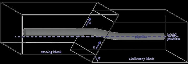
(a) pipeline deformation due to normal faulting
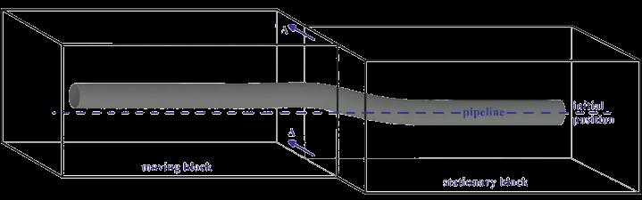
The protection scheme of buried pipelines at fault crossings results from a blend of regulatory provisions, engineering judgment, and the requirements of the pipeline owner. The general regulatory recommendations are (1) pipe rerouting to avoid environmentally sensitive and populated areas, (2) pipe orientation (selection of pipe–fault crossing angle) that results in pipe tension, rather than compression, (3) minimization of burial depth to reduce soil restrains on the pipe during movement in the trench, (4) avoidance of sharp bends in the crossing area that might act as anchor points, and (5) trench backfilling with appropriate soil material over a distance of 50 m on each side of the fault trace.
These recommendations stand as the “first line of defense” againsttheconsequencesoffaultingbutmight notbesufficientenoughtoensurethepipesafetyornot applicable due to environmental restrictions, the presence of physical obstacles, and regulatory restrictions.
(b) pipeline deformation due to reverse faulting
Thus, specific seismic countermeasures are typically required, the selection of which is based on a costbenefit analysis using appropriate variables, such as procurement and installation cost, pipe–fault crossing geometry, pipe owner specifications, and regulatory provisions.
(c) pipeline deformation due to strike-slip faulting
Fig. 1 Pipeline deformation caused by (a) normal, (b) reverse, and (c) strike-slip fault rupture (the left block is the moving and the right is the stationary one)

The fault mechanism, namely normal, reverse, or strikeslip, is the dominant parameter affecting the pipe
The protection of buried pipes at fault crossings might be seen as a trivial or very broad issue that is handled on a case-by-case basis. Nevertheless, a systematic investigation and examination of the available and proposed seismic countermeasures is necessary to assist pipeline designers and operators in selecting the appropriate measure for the case at hand.
RESE A RCH 10
The protection measures can be grouped into three categories based on the mechanism employed to achieve pipe strain reduction: (A) pipe strengthening, (B) soil friction reduction, and (C) complex measures. In more detail:
(A)Pipe strengthening can be achieved by steel grade upgrade to improve strength, wall thickness increase to improve pipe cross section stiffness, and pipe wrapping with composite wraps to increase strength.
(B) Thereductionofthefrictiondevelopedonthepipe–soil interface contributes to the reduction of pipe strains. This could be accomplished by trench backfilling with tire-derived aggregate that is a compressible material, use of geotextile-lined pipeline trenches (Fig. 2a), trench backfilling with loose granular soil (e.g., pumice), excavation of a wider trench for the pipeline to “freely” move in the trench (Fig. 2b), pipe isolation from ground displacements by placing the pipeline within concreteculverts andwithout backfilling material in the case of strike-slip faulting, and partial replacement of soil backfill with EPS geofoam blocks.

(C) Other measures that have been proposed or applied on a case-specific basis and can beclassified neither as pipe strengthening nor as friction reduction. These measures include the use of a protective device that aims at reducing the potential of local buckling by applying external hydrostatic pressure to the pipeline at critical predefined locations, the change of pipe route with a very high radius bend to allow unrestrained pipe deformation, the introduction of flexible joints in the pipeline at the fault vicinity (Fig. 2c) to “absorb” pipe deformation and render pipe segments virtually undeformed and consequently unstrained, the use of field bends to relieve pipe strains under very specific conditions by taking advantage of bends’ flexibility, and the creation of a predefined buckling pattern that consists of localized deformationofthepipewallatspecifiedpredefined locations aiming at controlling the pipe local deformation.
(c) Introduction of flexible joints at the fault vicinity

Fig. 2 Seismic countermeasures for pipelines at fault crossings
The selection of the appropriate protection measure is based on a set of criteria given the current legislation and the pipe owner’s specifications. A set of categorical criteria are defined to group the parameters that drive the selection and formulate a set of preliminary selection criteria (Table 1), which should be considered under the following remarks:

RESEARCH 11
(b) Construction of a wider trench
• Protection measures are applied along the entire fault trace uncertainty length, thus affecting the cost-related criteria.
• Weight factors should be applied if necessary, depending on the case at hand. For example, if the
crossing is located at a remote mountainous site, the transportation and installation costs might bevery high.
• More than one protection measure might be selected to satisfy the design objectives.
Category Criterion
1. Design
1.1 Compatibility with fault mechanism
1.2 Compatibility with pipe–fault crossing geometry
1.3 Compatibility with pipe cross-section geometry and steel grade
1.4 Requirement for sophisticated analysis
1.5 Requirement for experimental verification
1.6 Compatibility with codes
2. Construction 2.1 Ease of on-site application
2.2 Requirement for special installation equipment
2.3 Special requirements for transportation to the construction site
3. Procurement
3.1 Availability in the market
3.2 Production upon request
3.3 High cost of purchase
3.4 High cost of installation
Note: +: yes / compliance / required, x: no / not required, N/A: not applicable + Compatible only with strike-slip fault mechanism
Five protection measures, namely, wall thickness increase (pipe strengthening), pipe placement within culverts and backfilling with pumice (soil friction reduction), and introduction of flexible joints and route changing with high-radius bends (complex) are
indicatively examined using the selection criteria of Table 1. The compliance of each measure to every criterion is presented in Table 2, demonstrating thatthe selection process is a multi-level cost-benefit analysis.
by Vasileios E. Melissianos
RESE A RCH 12
Table 1 Preliminary selection criteria for pipe protection measures
Measure Design Construction Procurement 1.1 1.2 1.3 1.4 1.5 1.6 2.1 2.2 2.3 3.1 3.2 3.3 3.4 Wall thickness increase + + + x x + + x x + x x x Pipe placement within culverts x+ + N/A x x + + + + + + + + Backfilling with pumice + + + x x + + x + + N/A x x Introduction of flexible joints + + N/A + + x + x x + + + x Route changing with high radius + + + + x x x x N/A N/A N/A + +
Table 2 Illustrative examples of applying the preliminary selection criteria for pipe protection measures
Estimation of cable tension using measured natural frequencies
In tensile structures the estimation of cable tensile force is necessary to monitor the erection process at different construction stages, as well as to reliably assess the cables’ structural condition via regular inspections. Recently, the accuracy of cable force estimation through the free vibration method was
experimentally investigated at the Institute of Steel Structures. In particular, triggering free vibrations by handexcitation,thenaturalfrequenciesf(Hz)andcable tension T (kN) were simultaneously measured through a 3-axis accelerometer and a load cell.

Table 1 shows the cable cross-sectional properties and describes the experimental setup (fig. 2), where L=5.45m is the horizontal cable length, considered as
simply supported, m=0.2196kg/m is the measured cable weight per unit length and macc=0.10kg, mLC=1.10kg are the masses of additional equipment.

RESEARCH 13
Fig. 1 Experimental setup
Cable Φ
6x19
1520/1770
m(kg/m) macc(kg) mLC(kg) L(m) Lacc(m) LLC(m) 0.2196 0.100 1.100 5.450 Li 0.05
Table 1 Cable Properties
8
Prestressing steel
(EN 1992)
Fig. 2 Experimental setup
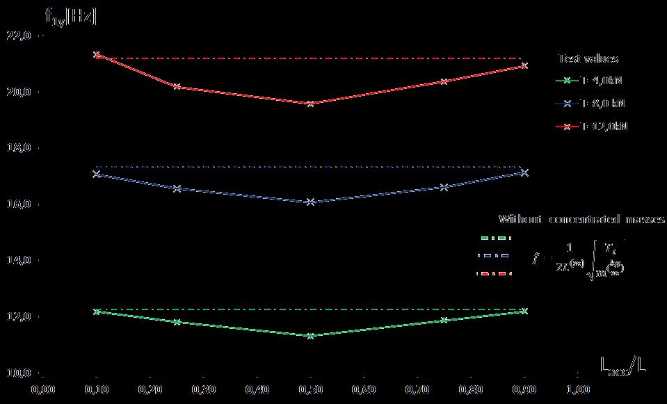
Dueto therelatively shortcable length,the presenceof instrument masses affects the measurement of natural frequency. In figure 3, the test values of out-plane
natural frequency for several cable forces and accelerometer positions along the length of the cable are presented and compared to the theoretical values
According to the string vibration theory, the response of the taut cable in the transverse direction can be described by the following equation:
where y(x, t) is the transverse displacement of the cable, t is the time and m(x) is the cable mass along the longitudinal direction, which is modified via a Dirac
signal function [1] to take into account the influence of instrument masses considered as concentrated. Τo determine the accuracy of the correlation between the measured natural frequency and the actual cable force, the experimental results and the theoretical values in terms of cable forces are compared. The comparison at various stress level σ(MPa) with the accelerometer positionat0.9Lisconducted,quantifyingalsotheeffect of load cell mass (Table 2, figure 4).
RESEARCH 14
Fig. 3 Comparison of measured and theoretical values of out-plane natural frequency as functions of cable force and position of accelerometer
�� ��2��(��,��) ����2 ��(��) ��2��(��,��) ����2 =0 (1)
Test Modified Analytical Equation f1(Hz) T(kN) Tmacc(kN) Error (%) Tmacc,mLC(kN) Error (%) 5.001 0.503 0.668 24,70 0.672 24,95 6.385 0.976 1.096 10,93 1.087 10,17 7.584 1.472 1.544 4,72 1.536 4,21 8.675 1.960 2.023 3,16 2.011 2,57 12.196 3.919 4.032 2,79 3.970 1,29 17.136 7.845 7.951 1,34 7.844 -0,01 20.939 11.777 11.916 1,17 11.707 -0,60 ����������=(1 ���������� ����������������������)��100
Table 2 Comparison between measured and theoretical cable tension
In figure 4 a lower stress level threshold can be detected, below which the relative error rate rapidly becomesunacceptable.Belowthisthreshold,theeffect of sag-span ratio and the variation of axial stiffness EI are not negligible and therefore the response is not governed by the simplified taut cable equation.
On the other hand, for higher exploitation level a good correlation between the experimental results and the theoretical values for engineering purposes (error<5%) is obtained.

The research is ongoing and cables of larger length, with various inclination and axial stiffness will be examined, investigating the aspects of the behavior
change with respect to stress level. Also, upgraded theoretical tools should be developed to validate the test results over the full range of axial stresses.
REFERENCES
1. Deyou Liu, Chenghui Jia, Bingjie Song, Dawang Li: Singular Function Model of Concentrated Mass-Cable Composite Structures, Journal of Vibration Engineering & Technologies (2022) 10:2657–2667
2. Byeong HwaKima,TaehyoParkb: Estimationofcable tension force using the frequency-based system identification method, Journal of Sound and Vibration 304 (2007) 660–676
by Konstantinos
RESEARCH 15
Fig. 4 Method error at several stress levels with accelerometer and with/without load cell mass effect
Mantas, Xenofon Lignos, Spyridon Papavieros, Ioannis Vayas
Investigation of corrosion effects on hollow steel sections
It is well known that corrosion is highly affected by environmental conditions. Towards a systematic investigation of corrosion effects on steel structures, a preliminary analytical investigation is presented here. A valuable contribution in this direction was made by Klinesmith et al. 2007 [1], who formulated an equation for the estimation of corrosion loss as a function of time and four environmental parameters. According to their work, the corrosion loss y, expressed in μm, as function of the exposure time t in years, can be obtained by:
Moreover, the proposed expression was validated via independently measured data and associated statistical processing.
It is observed that corrosion loss varies almost linearly withtime,astheexponentoftimeis0.98. Theproposed values of C, E, G and To are close to the mean values of ISO CORRAG program’s data for the corresponding environmental parameters TOW, SO2, Cl and T, respectively.Theproposedvaluesoftheotherempirical coefficients were obtained from measured data using the least squares method.
where TOW is the time of wetness in h/year, equal to the number of hours in a year during which the relative humidity exceeds 80% and at the same time the temperature is above zero, SO2 is the sulfur dioxide concentration in μm/m3, Cl the chloride deposition rate in mg/m2 , and T is the air temperature in oC. A, B, C, D, E, F, G, H, J are empirical coefficients. In their work the proposed corrosion loss equation has been formulated, and its parameters have been calibrated using data from ISO CORRAG research program [2], resulting, for carbon steel, in the following expression:


Minimum, mean and maximum values of the environmental parameters, as proposed in [1], are the following:

In order to assess the sensitivity of corrosion loss to each of the above four environmental parameters, a series of graphs is presented in Figures 1a to 1d, in each of which the minimum, mean and maximum values of one parameter are used, while for the other three parameters their mean value is adopted.

RESEARCH 16
Min Mean Max TOW 206 3819 8097 SO2 1 25 215 Cl 0.3 72 761 T -17 11 28
(a) Influence of time of wetness TOW (b) Influence of sulfur dioxide concentration SO2
(c) Influence of chloride deposition rate Cl
(d) Influence of air temperature T Fig. 1 Influence of environmental parameters on corrosion loss with time
In order to evaluate the effects of corrosion loss to the degradation of steel sections’ inertial characteristics, it can be easily confirmed by means of simple analytical calculations that for hollow circular and rectangular sections of uniform thickness t, the ratio of corroded (cor) to uncorroded (uncor) section area A, moment of inertia I and elastic section modulus W is equal to:
For the corrosion loss values calculated for the mean values of all 4 environmental parameters, the crosssection area, moment of inertia and elastic modulus ratioofcorrodedto uncorrodedsectionvarieswithtime as presented in Figure 2a as function of cross section thickness. The same effect for the maximum value of SO2 and the mean values of the other environmental parameters is illustrated in Figure 2b.
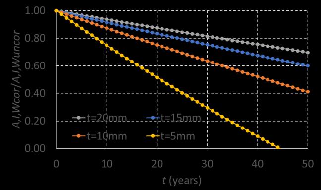


Hence, the effect of material loss y is the same for A, I and W, depending only on the uncorroded section thickness t and not on the section dimensions.
In the following steps of this investigation, it will be attempted to confirm these analytical findings with accelerated corrosion tests in the Institute’s corrosion chamber.
(a) Mean values of all environmental parameters
(b) Max value of SO2 and mean values of other parameters
Fig. 2 Influence of corrosion on degradation of inertial characteristics of hollow sections
REFERENCES
[1]Klinesmith, D.E., McCuen, R.H. and Albrecht, P. (2007). “Effect of environmental conditions on corrosion rates”, Journal of Materials in Civil Engineering, ASCE, 19(2), pp. 121-129.
[2] Dean, S.W. and Reiser, D.B. (2002). “Analysis of longterm atmospheric corrosion results from ISO CORRAG program” Outdoor atmospheric corrosion, ASTM STP 1421, H. Townsend, ed., ASTM, 3-18.
by Aikaterini Ntaifoti & Charis Gantes
RESEARCH 17
�������� ������������ = �������� ������������ = �������� ������������ =1 �� ��
Earthquake sequence in Kahramanmaraş, Turkey - Reconnaissance report
On 6th February 2023 two major earthquakes hit the south-centralregionofTurkeyandnorth-westregionof Syria. The first earthquake hit at 4:17 local time with a magnitudeof7.8ontheRichterscale,withitsepicentre in the Pazarcık district of Kahramanmaraş province (37 km west of the city of Gaziantep). A second major earthquake with a magnitude of 7.5 occurred 9 hours later with an epicentre 95 km north of the first one (Figure 1). The two earthquakes affected a vast area with apopulationofalmost16million people,including 1.8 million Syrian refugees. Based on the official numbers, the death toll in the two countries is staggeringatalmost60.000people.Inadditionto being one of the deadliest earthquakes of modern time, the damages are also difficult to grasp. More than 50.000 buildings collapsed or await demolition. 200.000 were severely damaged and almost 50.000 were moderately damaged. Over 2 million people had to live in temporary shelters and an additional two million were forced to move to non-affected regions. All these numbers prove that it will take a significant amount of time, funds and socialeffort to heal thescars left bythe earthquake sequence.
At the face of this unprecedent catastrophe, the Greek people did not stay impassive towards the Turkish and Syrian people. Significant humanitarian aid was sent towards the affected regions from various organisations and bodies of the regional and national government. In addition, a unit of the Disaster Response Special Unit (Greek initials ΕΜΑΚ) was sent to help save people from the collapsed structures during the first crucial days of operations. The Greek scientific community was also eager to help. A lot of people from the academic and professional society of civil engineers immediately volunteered to participate in a mission to Turkey in order to investigate the affected regions and help in any way that would be beneficial for the neighbouring country. After establishing the scope of the mission and overcoming the difficulties of organising such a demanding task, the Greek Reconnaissance Mission was established, consisting of 10 members of the National Technical University of Athens, including the author, and 7 members of the
Hellenic Association for Earthquake Engineering (Greek initials ΕΤΑΜ). The trip was made possible through the organising and financial aid of the Technical Chamber of Greece (Greek initials ΤΕΕ) and ETAM, while Turkish Academics and the Prime Ministry Disaster and Emergency Management Authority (Turkish initials AFAD) played a crucial role with the invitation and clearances of the Greek mission, while they also established the areas that should be visited and the means to contribute to the Turkish efforts.
The17membersofthemissionlandedatAdanaAirport on21st April2023andtravelledtoGaziantep,whichwas the base of operations, in the middle of the affected region. The programme of the mission, which covered more than 1500 km (Figure 1), was as follows:

- Day 1 (21/4): Adana, Gaziantep
- Day 2 (22/4): Pazarcık, Gölbaşı, Adıyaman
- Day 3 (23/4): Kahramanmaraş, Türkoğlu
- Day 4 (24/4): Antakya, Iskenderun, Dörtyol
- Day 5 (25/4): Nurdağı, İslahiye, Adana
The main interest of the mission was twofold. On one hand, the geotechnical/geological aspects like the surfacing and propagation of the fault were
FIELD MISSION 18
Fig. 1 Map of south central Turkey with the epicentres of the two main events and the main sites that were visited by the Greek Mission
investigated, as well as phenomena like liquefactions and extreme settlements. On the other hand, the structural condition of the buildings in the cities that were most severely hit was investigated. To that end, almost 500 buildings were examined with rapid visual inspection and logged with the AFAD mobile app (ArcGIS Survey 123) to a central database. In addition, most of these buildings were also logged with a Greek app (SAFER – Post-Quake RVI) to be included to the free-access database that ETAM has been creating in the past, during similar missions in Greece and the neighbouring countries.
The vast majority of the structures that were assessed during the mission was masonry and reinforced concrete (RC), with the latter being the main structural material for modern structures. The extent of the damage can be attributed to several causes. First and foremost, the magnitude of the two back-to-back events, but also the high number of old buildings with hardly any seismic design (e.g. smooth reinforcing bars or insufficient transverse reinforcement). The dense construction in the cities led in many cases to severe pounding,wherethebuildingsthatcollapseddestroyed parts of the neighbouring structures and even cut columns or shear walls. Certain structural systems (like the flat slab-column with no beams, see Figure 2) seem to have performed quite poorly.
Finally, the lack of quality control of the structures seems to be amajor factor in the extent ofthe damage, covering aspects like quality of concrete and bricks, detailing of reinforcements and poor compliance of modern buildings design and constructionto thecodes.

As far as steel structures are concerned, not many conclusions could be derived, as structural steel is not very popular in the affected regions, but also in Turkey in general. In fact, as it can be seen in Figure 3, types of structures excluding RC and masonry and including structural steel, are less than 1% of the total building stock.

This is much more intense in residential buildings, which comprise the main majority of the structural stock, while steel structures comprise a noticeable percentage of the new non-residential buildings, which cover other uses like commercial, industrial, educational etc. As a result, not many steel structures wererecorded,andmostofthembehavedasexpected, especially if they were code-designed rather than built based on experience, which was the case for some small-scale industrial buildings and warehouses.
Roof structures behaved very well, which is normal for such lightweight structures (Figure 4). In addition, as they remainedsafeand fully functional,they wereused to cover tents providing civil services, a function which was of paramount importance in the regions that were hit.
FIELD MISSION 19
Fig. 2 Partial collapse of a 9-storey flat slab RC building, Adıyaman
Fig. 3 Distribution of buildings by their structural system (Gunes 2015, TUIK)
A very common practice was for the last floor of multistoreyRCbuildingstobecoveredwithasteelroof.Even in cases where the main buildings were heavily damaged and despite the increased spectral acceleration at the top, these roofs behaved quite well, especially if they were connected to a concrete part in the centre of the top floor. However, a few of those structures failed, due to the lack of adequate bracing and insufficient anchorage of the columns (Figure 5).
A RC building which was retrofitted with steel frames in its second storey was found in Antakya. Although the building did not collapse, the plasticity demand was mostlyconcentratedinthesecondfloor.Thus,thesteel members suffered significant permanent deformation and the non-structural elements were completely destroyed, probably deeming the building beyond repair (Figure 6).


As far as bridges are concerned, no significant damages were observed other than the activation of the seismic stoppers and small permanent deformations of the bearings. This was even better for steel bridges, which mostly remained fully functional, except of damage to secondary members, façade and parapets (Figure 7). Most of these cases were recorded in Antakya, which was probably the city that was most severely hit on 6th February.


As a general conclusion, despite the devastating magnitude of the earthquakes that hit Turkey, steel structures performed generally well or as expected, especially when designed according to modern codes. Therefore, the possibility of steel structures claiming a bigger ratio of the building market should be investigated for certain categories, i.e. residential

FIELD MISSION 20
Fig. 4 Roof structure of the municipal market, Nurdaği
Fig. 5 Total collapse of top floor steel roof due to insufficient anchorage and bracing, Pazarcık
Fig. 6 Retrofitted RC building with steel members, Antakya
Fig. 7 Pedestrian truss bridge with non-structural damage, Antakya
buildings with more than 8-10 storeys, industrial, administration, education buildings etc. Significant attention should be paid to the structural detailing and quality of construction to ensure good behaviour in the future.
You can find additional information regarding the observations and findings of the Greek reconnaissance mission in the presentations of an international webinar that took place on 12th July, and can be found in the following YouTube list.
On a personal note, our hearts and thoughts are with the Turkish and Syrian people, along with our hopes for a swift recovery.
REFERENCES
1. Reliefweb, Turkey-Earthquake: Emergency Situation Report (06.04.2023), https://reliefweb.int/report/turkiye/turkeyearthquake-emergency-situation-report-06042023
2. Gunes O., Turkey’s grand challenge: Disaster-proof building inventory within 20 years. Case Studies in Construction Materials 2, 18–34, 2015.

3. Ay B.Ö., Eroğlu Azak T., Erberik M.A., Evaluation of Changing Building Characteristics in Turkey. ACE 2016, 12th International Congress on Advances in Civil Engineering, Istanbul, Turkey, 2016.
4. https://www.youtube.com/watch?v=3cY6UBPTOH4 &list=PLeMIVks4v35qOLMkD8cU1aikP2oHW95Vi
by Pavlos Thanopoulos
FIELD MISSION 21
The members of the Greek reconnaissance team in front of the mountain-scale landslide near İslahiye. From left to right: Aristidis Papachristidis, Marina Moretti, Ziya Cekinmez, George Gazetas, Anastasios Sextos, Manolis Vougioukas, Pavlos Thanopoulos, Panagiotis Tsopelas, Evangelia Garini, George Tsiatas, Dimitrios Pitilakis, Vasiliki Palieraki, Christos Zeris, Vasilis Marinos, Christos Giarlelis, Sotiria Stefanidou and Elissavet Vintzileou


ISS Institute of Steel Structures National Technical University of Athens School of Civil Engineering Institute of Steel Structures 9 Iroon Polytechneiou str. Zografou Campus, 15780 Athens - GREECE
