14 minute read
Sucker Rod Pumping System for Deep High Volume Wells

Abstract
Worldwide there are almost 920,000 producing oil wells, about 87% of these wells are operated using diff erent arti fi cial lift methods and roughly distributed as: 71% are producing using beam pumping system, 14% using electrical submersible pumping (ESP), 8% using gas lift and 7% using all other forms of lift ing systems.
Advertisement
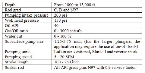
This study was undertaken using advanced predicti ve methods, high strength rods, opti mum pumping mode, and unit geometry to opti mize the performance of beam pumping systems for deep high volumes oil wells. Three geometries of diff erent surface pumping units were analyzed and studied including, conventi onal, Reverse Mark and Mark II units. Each geometry of those three types has been subjected to diff erent design features that aff ect torque and diff erent linkages aff ecti ng its kinematics behavior. The highest strength sucker rod string, beam unit geometry, stroke length, pumping speed and subsurface pump size were varied and analyzed jointly to obtain opti mum pumping parameters capable to produce maximum fl uid at diff erent well depths. This study has also considered and applied many other variables including; well depths from 1,000 to 15,000 ft , three diff erent rod grades, water cuts from 0.0 to 100%, diff erent pump sizes from 1.25 to 5.75 in, stroke lengths from 100 to 260 in, and non-API sucker rod grades.
The results indicated that the lift ed liquid volumes and pump seati ng depths for deep wells can be eff ecti vely increased using the beam pumping systems. The surface unit geometry has shown a crucial eff ect of increasing the produced quanti ty from deep wells. The study recommended using conventi onal pump unit for shallow depths up to 8,000 ft . The enhanced geometry pumping units of Mark II and reverse Mark have been proven to be the superior type when it comes to dealing with deep high volumes wells because it requires the least torque to lift the same quanti ty from diff erent well depths. The study also presented successful fi eld applicati ons for deep wells producing high volumes.
08 March 2011 ECHO Mohammed Ghareeb Lufk in Industries
Introducti on
Downhole pumps are a common means for enhancing the producti vity of a well by reducing the bott om hole pressure. Two types of pumps are used including positi ve-displacement pumps (which include sucker rod pumps and hydraulic piston pumps) and dynamic displacement pumps (Economides et al, 1993).
Beam pumping system is the fi rst and may be the last arti - fi cial lift system. A century ago the most universal mechanism for arti fi cially lift ing fl uid was the standard Shadoof. The earliest documented walking beam and sucker rod pumping system is described in Egypti an historical writi ng dated 476 AD.
In the past, the ability of beam pumping systems to produce high volumes from deep wells was limited due to two main reasons:
(1) the high rod and fl uid loads. (2) the lack of deep understanding of the behavior of complex sucker rod system and the involved nature of the reservoir with its contained fl uids and infl ow performance.
Nowadays, the existence of the following elements leaded to producing high volumes of producti on from deep wells:
87% of oil wells are arti fi cially lift ed:
71% beam pumping system
14% electrical submersible pumping
08% gas lift
(1) development of relati vely long stroke with enhanced geometry pumping units that have good quality tensile strength sucker rods as well as more accurate predicti ve soft ware. (2) accurate on-site monitoring and control tools. (3) pumping using large plungers with high pumping speeds.
The ability of a sucker rod pumping system to produce a fl uid is constrained by:
(1) the stroke length. (2) the rod free fall from a given well. (3) the plunger diameter of the bott om-hole pump. (4) the strength of the sucker rods. (5) unit geometry.
For any given unit geometry, criti cal pump speed is controlled by two variables: (1) stroke length. (2) the well forces, such as fricti on, buoyancy, etc., that retard rod fall (Byrd, 1968).
Byrd (1968) reviewed some fi eld studies to conclude the practi cality of high volume producti on with sucker rods. He reported that the new development in pumping units with 240-in maximum stroke had structural capacity exceeds 47,000 lb, with a torque rati ng greater than 2.5 million in-lb, which is capable of producing quiet high volumes from relati vely deep wells. He also indicated that practi cal sucker rod pumping approaches 13,000 ft , and capaciti es of producing 5,000 and 6,000 B/D from shallow to medium depths easily. In additi on, volumes of 9,500 B/D were considered practi cal with sucker rod pumping equipment at that ti me. The study did not cover the rod buckling tendency, as it will be covered in this study.
In the present, the structure and geometry of a modern pumping unit reaches 260-in maximum stroke with structural capacity exceeds 47,000 lb, and the torque rati ng greater than 2.5 million in lb. The plunger diameter for some bott om-hole pumps (casing type) runs as high as 5.25 in, a bigger size can be built based on the manufacturing capacity. It might be the greatest improvement in the sucker rod, which may have a tensile stress of some 150,000 lb. termine the system capabiliti es to produce maximum practi cal fl uid from diff erent depths, 1000 ft to 15,000 ft . Since sucker rod strength is the limiti ng factor in high volume beam pumping, the highest strength sucker rod string, the beam unit geometry, stroke length, pumping speed and subsurface pump size were analyzed jointly to obtain opti mum pumping parameters to produce maximum fl uid at diff erent depths of the well. Table1 presented the criteria used in the design.
Table. 1. Criteria used in the design.
A number of general assumpti ons were applied in making these calculati ons:
(1) In all cases the tubing was considered anchored, thus no tubing stretch.
(2) Casing can accommodate the required tubing size.
The system was designed for three diff erent cases as follows: (1) All the produced fl uid was water with fl uid gradient of 0.433 psi/ft .
(2) The system produced fl uid with 50% water cut where gas/liquid rati o (GLR) is zero.
(3) The system produced fl uid with 100% oil and Gas/Oil rati o (GOR) is zero.
Three diff erent surface pumping units geometries were studied including, conventi onal, Reverse Mark and Mark II units. Each of these three geometry units has diff erent design features that aff ect torque and diff erent linkages that aff ect its kinemati cs behavior. Because each well is diff erent, one of these unit types
Beam pumping system is the fi rst and may be the last arti fi cial lift system. A century ago the most universal mechanism for arti fi cially lift ing fl uid was the standard Shadoof. The earliest documented walking beam and sucker rod pumping system is described in Egypti an historical writi ng dated 476 AD.
System Design Considerati ons
The typical sucker rod system design involves using a predicti ve computer program (API or wave equati on) to generate possible soluti ons for sizing the surface and subsurface equipment. Based on the fi eld and engineering experiences, if the producti on predicted by the program is acceptable, without exceeding the equipment limitati ons and rod running without buckling, then the design is completed.
This study was made using SROD soft ware (Lufk in) to demay out perform in comparison to the others for a given set of well data and for the end user’s design goals. When designing a Beam Pump installati on, diff erent geometries were considered to determine the best performance for the intended result.
Result and Discussion
Figure 1 compares the capacity of the three diff erent geometries and indicates that at shallow well depths of 1,000 and 2,000 ft , the conventi onal unit produces higher producti on than or at least comparable to the other two types. This

pumping parameters having impact on pumping rate and included in the design of the rod string as well. At this point the rod string is designed by setting the rod stresses equal at the top of each taper section for high-strength rod materials. These parameters are checked against the limiting factors:
(1) Peak polished rod load versus the unit’s allowable structural load.
(2) Peak net torque vs. the speed reducer’s torque rating. (3) Pumping speed is compared to its critical value by checking the calculated minimum polished rod load. Obviously, critical pumping speed is detected when minimum polished rod load approaches zero as a result of the carrier bar leaving the polished rod clamp.
(4) Rod buckling, Sinker bar is considered for rod string shown tendency of buckling.
Fig. 1. Comparison the capacities of the three different geometries.
As shown by Figure 1, and as might be expected, in general, in high production rate, shallow wells, the conventional pumping geometry works good and it can handle up to more than 8200 BFPD with the subsurface pump seated at 1000 ft depth and dynamic fluid level about 1500 ft from surface. This value of production is not the end limit of the equipment, unit, rod and tubing all can handle more volume. For example in order to produce 8,200 BFPD the calculated required torque was 1,190,000 in-Ib and the peak polished rod load was 20,346 Ib. Then still there is a room for more torque and structure load In comparison with the current present units which can handle up to 1,820,000 in-Ib and 47,000 peak load.
Consider the rod string condition, the rod string was grade D loaded with 80% of its maximum load. Even the rod still can lift more loads, where still 20% room in that grad and more than 50 % for the ultra high strength rods. The size of the subsurface pump was 5.75 in. All those numbers show that there is no problem of the equipment to handle more volume.
For deep well, high tensile rod string is used in the design. For that high tensile rod string, it is extremely important to design rod string taking into consideration rod handling. If there is any corrosion environment expected, an effective chemical treatment is recommended. However currently in the market, there is a quite high quality sucker rod which can withstand corrosion for a certain limit suck as grade KD 90.
Many studies in the literatures (Derek et al., 1988; Pope, 1993) and field practices (Nolen, 1969; Wan, 1986, Murtha et al, 1987), concluded that the enhanced geometry pumping systems has been proven to be an economically feasible type when the unit is capable to lift fluid form medium to deep wells (+6000 ft) and this type geometry features create a more uniform torque (usually create less peak torque for a given set of well conditions than a conventional unit).
The design shows that fluid lifting capacity of a rod pumping system is limited by several factors. The main limiting factors are:
(1) the pumping speed. (2) the strength of the rod material. (3) the structural capacity of the pumping unit. (4) rod buckling.
Effect of Surface Unit Geometry
The design output match with all published literatures (Allen, 1969; Gibbs, 1977; Murtha et al., 1987; Derek et al. , 1988; Pope, 1993) and field practices (Nolen, 1969; Wan, 1986, Murtha et al, 1987), where all agreed that the enhance geometry pumping systems proved to be the economical type of pumping units lifting fluid form medium to deep wells. Where geometry features of that type create a more uniform torque and thus usually create less peak torque for a given set of well conditions than a conventional unit. It normally requires less motor horsepower and uses less energy than a conventional unit doing the same work. Figures 2, 3 and 4 present a comparison of required torque, peak polished rod load, and required motor power of the three above-mentioned pumping unit’s geometries for different well depths, respectively. The comparison was based on attaining fixed target production at three different depths, of 200, 700 and 1,500 BFPD at 5,000, 10,000 and 15,000 ft depth, respectively.
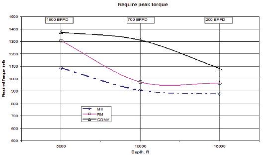
Fig. 2. Required peak torque versus depth.
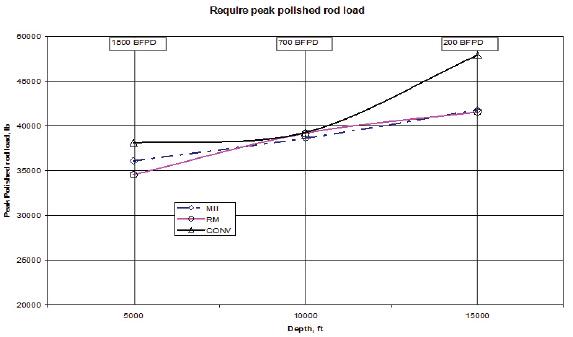
Fig. 4. Required motor power versus depth.
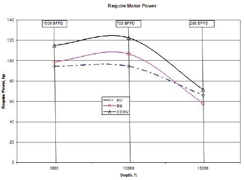
As shown in Figure 2, the MII pumping unit is the superior unit as the least required torque to lift the same quanti ty from the diff erent depths while the conventi onal one showed poor performance. This is because, the front mounted Class III lever system geometry of that unit insure opti mum torque carrying capacity. The reverse mark geometry lies in the middle between the Mark and the conventi onal type. With respect to the load as shown in Figure 3, it is shown that up to about 8,000 ft the reverse Mark geometry require the lowest load to lift the same quanti ti es of fl uids. More than 8,000 ft and up to about 13,000 ft MII will require less but not far than the RM geometry and sti ll the conventi onal far than the two geometries. All those refl ect in the required motor power as shown by Figure 4.
Conclusions
This simulati on study was achieved using actual fi eld data. It analyzed and studied the performance of conventi onal, Reverse Mark and Mark II pumping units under diff erent well conditi ons and variable pump characteristi cs. The following conclusions can be drawn as follows:
(1) The depth from which beam pumping system eff ecti vely lift fl uid can signifi cantly be increased by using high strength rods, opti mum pumping running parameters and enhanced unit geometry.
(2) The problems of lift ing high rates from shallow wells are quite diff erent than that of lift ing from deep wells. Therefore, the use of modern equipment and operati ng practi ces allow fairly large volumes to be pumped.
(3) The conventi onal pumping unit is recommended for shallow well depths up to 8,000 ft because it provides the highest quanti ty under the same operati ng conditi ons of Mark II and Reserve Mark pumping units.
(4) The Mark II pumping unit has provided the superior lift ed quanti ty than other types of Reverse Mark and conventi onal ones because it required the least torque to lift the same quanti ty from diff erent well depths up to 8,000 ft .
(5) Historical cases have proven successful applicati on of producing high volumes from deep wells using diff erent bean pumping systems.
___________________________________________________ References 1. Takacs, G.: Sucker-Rod Pumping Manual. PennWell Books, Tulsa Oklahoma, 2003. 2. Clegg, J. D. “High-Rate Artifi cial Lift” Journal of Petroleum Technology (March): 1988, pp. 277-82 3. Lufkin Industries Inc., http://www.lufkin.com/oilfi eld/index. html 4. Byrd, J. P. High volume Pumping Sucker Rods, SPE 2104, The SPE Eighth Secondary Recovery Symposium, Wichita Falls, TX, USA, May 6-7, 1968,. 5. Byrd, J. P. “Pumping Deep Wells with a Beam and sucker Rod System.” SPE 6436. Amarillo, Texas: Deep Drilling and Production Symposium of the Society of Petroleum Engineers, April 17-19, 1977. 6. Economides, M. J., Daniel, A. D., Ehlig-Economides, C. Petroleum Production Systems, Prentice-Hall of Australia, Sydney, 1993. 7. Gott, C. I. “Successful Rod Pumping at 14,500 ft” SPE 12198. San Francisco, California: 58th Annual Technical Conference and Exhibition of the Society of petroleum Engineers, October 5-8, 1983. 8. Ditmore T. L. “Field Operating Experience Using New UltraHigh Strength Sucker Rods” SPE 4536, Fall Meeting of the Society of Petroleum Engineers of AIME, 30 September-3 October, Las Vegas, Nevada, 1973. 9. Lufkin Automation, http://www.lufkinautomation.com/srod. asp
Mohammed Gharib is Eastern Hemisphere Technical Director Arti fi cial lift Applicati ons arti fi cial lift
expert - Middle East and North Africa for Lufk in Industries, Inc. Gharib has been with Lufk in for 5
years and has worked in design, opti mizati on, service, and sales. He has also spent a good part of his
career analyzing wells and recommending acti ons to be taken to opti mize diff erent arti fi cial lift sys
tems (ESP, Sucker rod, PCP, and Jet) and enhance well performance. He has spent 19 years working
with Agiba Petroleum Company before he joined Lufk in. He is a producti on engineering and opera
ti ons lecturer for two diff erent universiti es in Egypt. He is SPE - Egypti an Secti on program chairper
son. He published and presented several technical papers.


