1 minute read
General


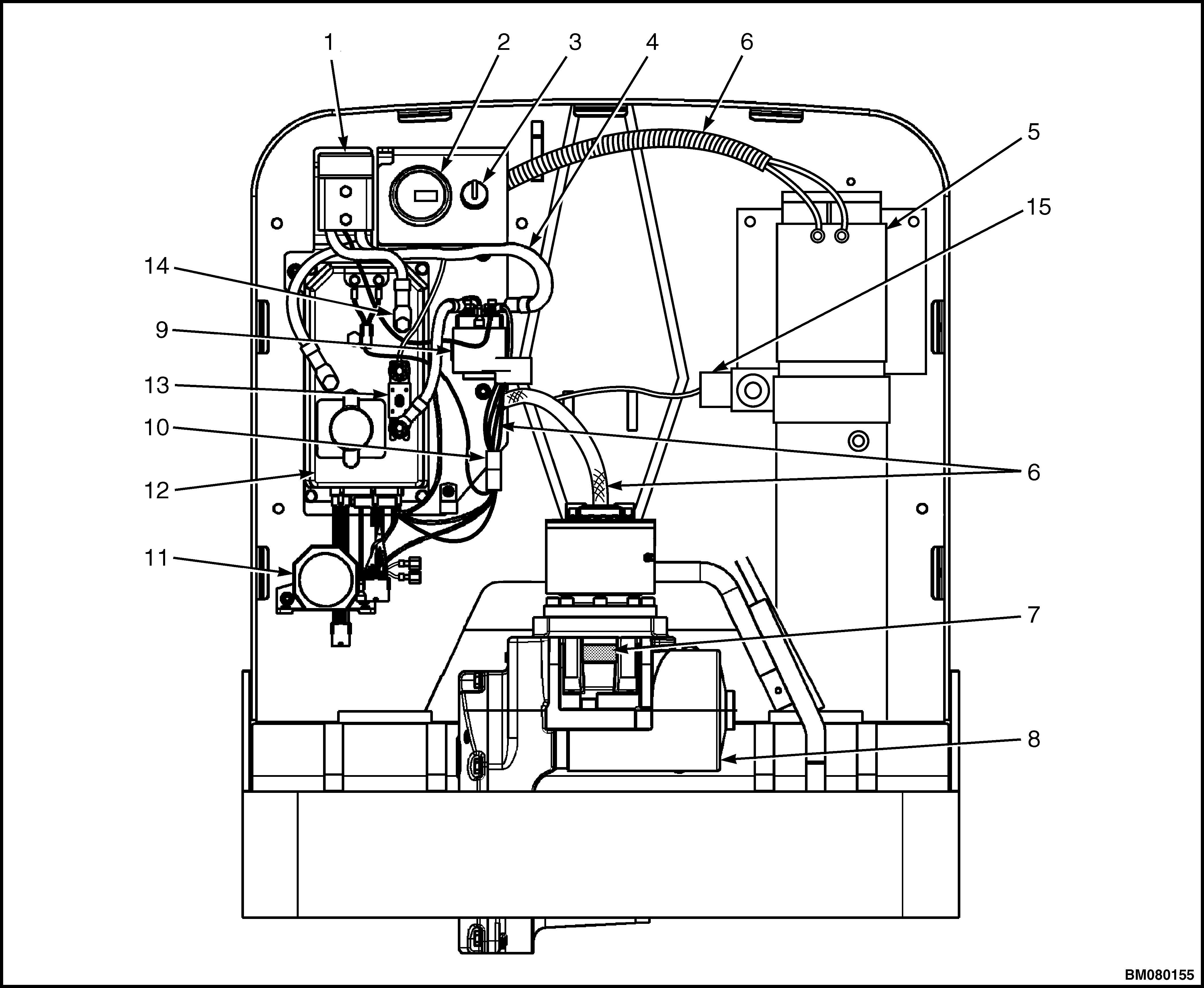
This section includes removal, disassembly, checks, adjustments, assembly, and installation procedures for the electrical system components on the W20-25ZA [A495], W25-30ZA2 [B495], W40Z [B218], W45Z [C215], and W50Z [D215] truck models. This section does NOT include the electrical components covered in other sections such as motors and industrial batteries. See Figure 1.
See the section ZAPI™ Controllers 2200SRM1064 for models W20-25ZA [A495] and W25-30ZA2 [B495] ; ZAPI™ Controllers 2200SRM1006 for models W40Z [B218]; ZAPI™ Controllers 2200SRM1067 for models W45Z [C215] and W50Z [D215] for models for additional information on the ZAPI™ display and for information on troubleshooting fault codes, adjusting parameters, and testing the ZAPI™ motor controller. See the section DC Motor Maintenance 0620SRM0294 for general information on DC motors. See the section Periodic Maintenance 8000SRM1048 for models W20-25ZA [A495]; Periodic Maintenance 8000SRM1009 for models W40Z [B218], W45Z [C215], and W50Z [D215]; Periodic Maintenance 8000SRM1379 for models W25-30ZA2 [B495].See the section Diagrams 8000SRM1050 for models W20-25ZA [A495]; Diagrams 8000SRM1011 for models W40Z [B218] and W45Z [C215];Diagrams 8000SRM1228 for models W50Z [D215]; Diagrams 8000SRM1381 for models W25-30ZA2 [B495].
Advertisement
1. BATTERY CONNECTOR 2. BATTERY INDICATOR/HOURMETER DISPLAY 3. KEY SWITCH 4. POSITIVE BATTERY CABLE 5. LIFT PUMP MOTOR 6. WIRING HARNESS 7. CONTROL HANDLE ARM PROXIMITY SWITCH 8. DRIVE MOTOR 9. MAIN CONTACTOR 10. CONTROL FUSE 11. HORN 12. ZAPI™ MOTOR CONTROLLER 13. POWER FUSE 14. NEGATIVE BATTERY CABLE 15. LOWERING VALVE