1 minute read
Install


3. Remove the upper drive unit compartment cover.
4. Remove the lower drive unit compartment cover.
Advertisement
5. Remove the four capscrews from the two-piece shield over the MDU and remove the shields.
6. Discharge the capacitor. See Special Precautions.
7. Cut the tie wrap located at the end of the proximity switch harness.
8. Remove the proximity switch harness clamp, located beneath the drive unit housing.
9. Disconnect the proximity switch from the wiring harness.
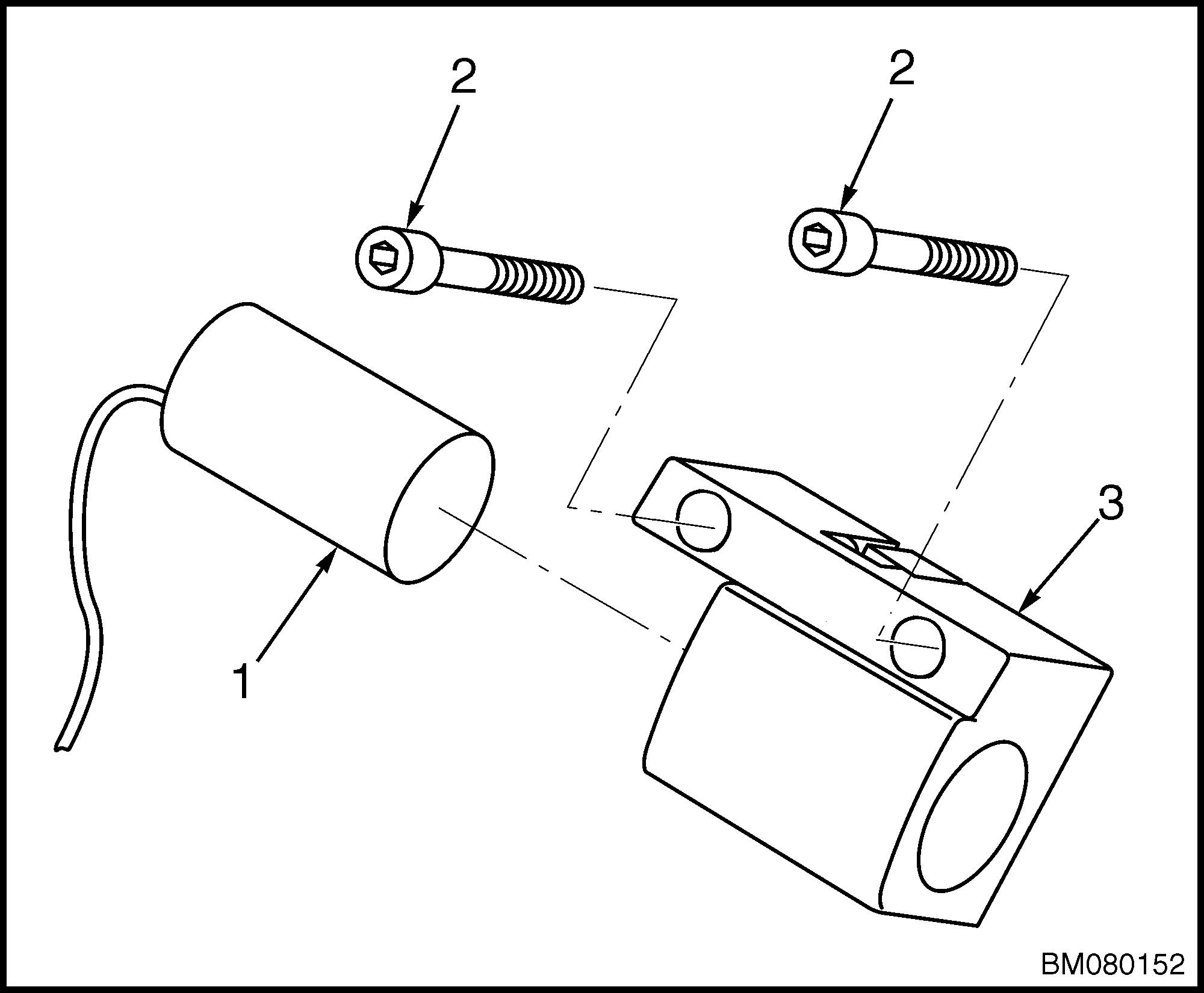
10. Fully lower the control handle arm. Remove the two capscrews that mount the proximity switch assembly to the control handle arm. See Figure 10. Remove the proximity switch assembly.
1. PROXIMITY SWITCH 2. CAPSCREW 3. SWITCH BRACKET
Figure 10. Proximity Switch Assembly
Install
1. Insert the proximity switch fully into the switch bracket. Route the proximity switch wire so that it will not be pinched or damaged when the control handle is installed.
CAUTION
DO NOT damage the plastic switch bracket or proximity switch by overtightening screws.
2. Install the proximity switch assembly to the drive unit housing with two capscrews through the switch bracket into the drive unit housing.
DO NOT tighten the capscrews until after the switch has been adjusted.
3. Check the gap between the proximity switch assembly and the control handle. The gap should measure 3.0 to 5.0 mm (0.12 to 0.20 in.) See
Figure 11. If the gap distance is different, horizontally adjust the location of the proximity switch.
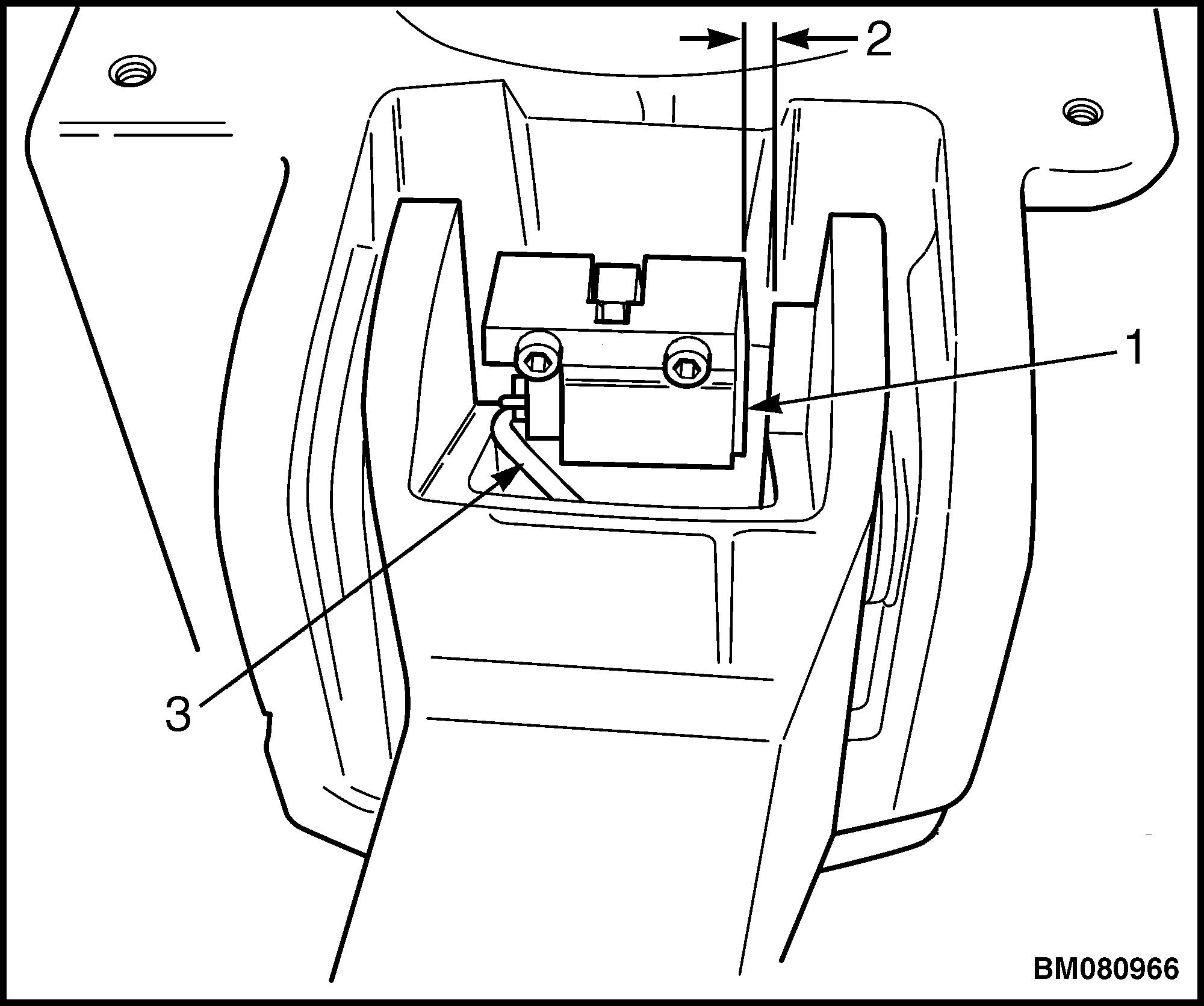
1. PROXIMITY SWITCH ASSEMBLY 2. GAP 3.0 TO 5.0 mm (0.12 TO 0.20 in.) 3. PROXIMITY SWITCH WIRE
Figure 11. Proximity Switch Assembly Location
4. Connect the switch to the wiring harness.
5. Connect the battery and turn the key switch to the ON position.
6. With the handle at 10° from vertical, move the proximity switch until the LED turns on.
7. Slowly move the proximity switch in the opposite direction until the LED just turns off.
8. Torque the two capscrews to 4.17 N•m (37 lbf in).