3 minute read
Description of Operation


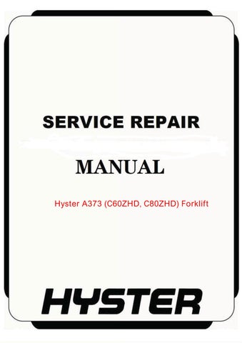
A. RH SIDE B. LH SIDE C. FORWARD D. REVERSE
Figure 1. Truck Orientation
Advertisement
This section includes information on the following components: • Control Handle Switches • Hall Effect Directional/Speed Control • Key Switch • Parking Brake Switch • High Speed Switch • Hand Brake Assembly (Brake and Regen
Switches) • Battery Discharge Indicator/Hourmeter (BDI) • Fuses
• Control Module • AC Motor Controller • Brake Coil • Drive Motor • Lift Pump Motor (C60-80ZHD) • Contactor
ON/OFF switches are used for: • Key Switch • Lift and Lower Functions (C60-80ZHD) • Horn • Fast Speed (Foot Switch) • Brake and Regen Switches • Throttle Neutral Signal • Parking Brake
A directional/throttle control, neutral switches, and push-button function switches are housed in the control handle.
The Hall effect throttle control is used to provide a directional/speed signal. The neutral switches verify the throttle is in neutral position during the self-check at startup. The horn switch (and lift and lower switches on the C60-80ZHD) are mounted in the top cover of the control handle. These switches send signals to the controller activating each individual function.
The control module converts analog signals from the control handle to digital signals for the controller to read.
The main contactor opens to remove power from the traction and lift circuits in the event of an electric failure.
A spring applied/electrically released brake is mounted to the top of the traction motor. When the key switch is in the ON position and the parking brake switch is in the OFF position, the brake coil energizes, disengaging the brake. This pulls the brake pressure plate away from the friction disc allowing the drive motor to turn freely.
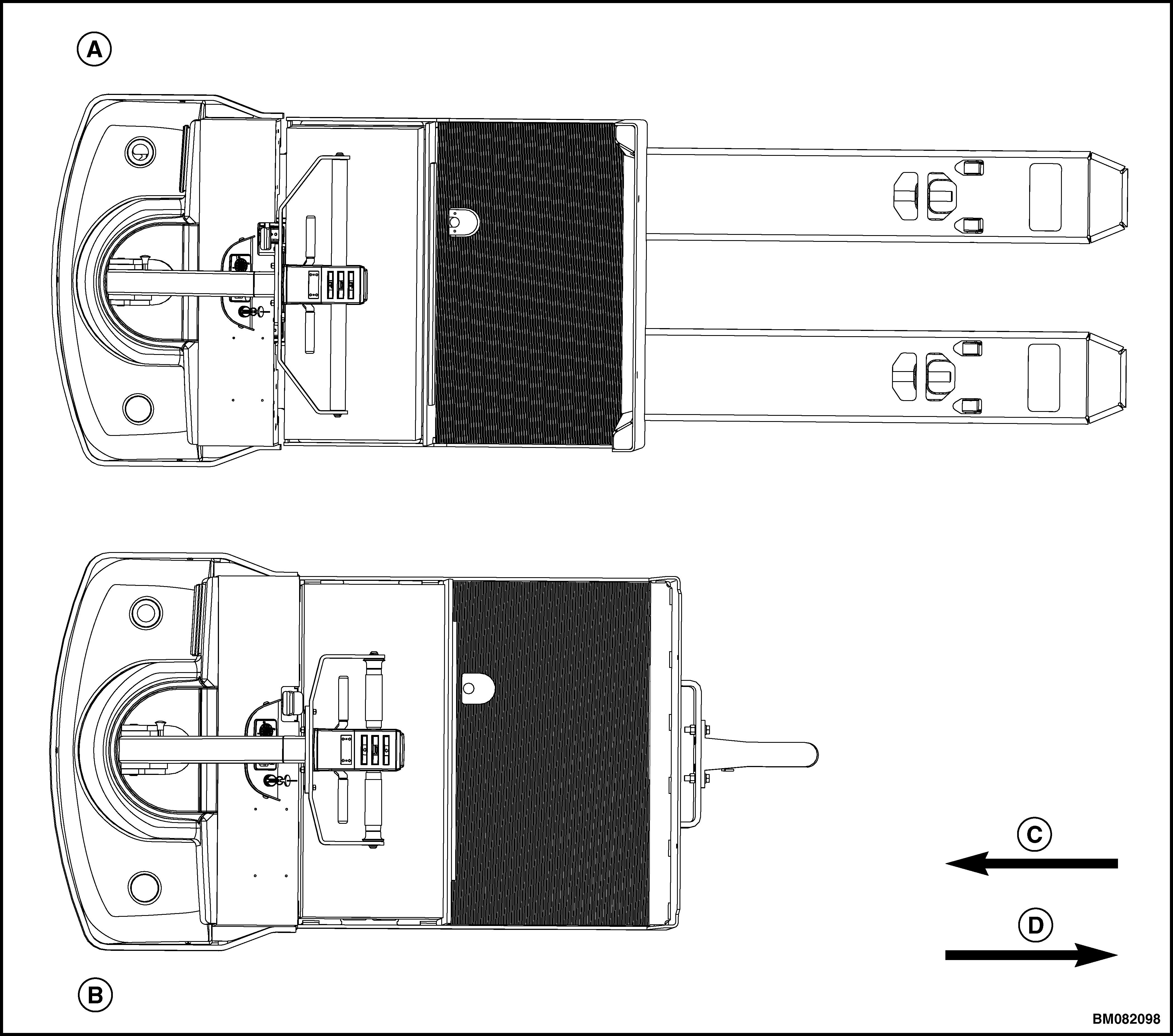
A two-stage hand brake assembly (see Figure 2) is mounted just below the control handle. The hand brake assembly consists of two independent hand levers, various linkages, and three switches to perform two different braking functions. When both levers are released (Position One), no braking is applied. If either hand lever is placed in the second position, the controller places the traction motor into regen mode.
The brake coil releases the pressure plate mechanically engaging the brake when either hand lever is placed in the third position, the parking brake switch is in the ON position, or when the key switch is in the OFF position.
1. BRAKES DISENGAGED (POSITION ONE) 2. REGENERATIVE BRAKING (POSITION TWO) 3. MECHANICAL BRAKING (POSITION THREE)
Figure 2. Hand Brake Position
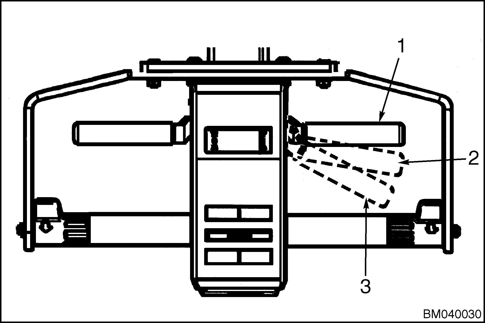
On the C60-80ZHD trucks, the motor controller energizes the lift pump motor when the lift button is depressed. The motor controller activates the solenoid coil opening the lowering valve (located at the pump), when the lower switch is depressed. Refer to Figure 3 or Figure 4. The controller protects the lift pump and motor assembly, eliminating the need for a height limit switch. The controller will stop the lift pump motor 0.6-0.8 seconds after current flow to the lift pump motor exceeds the preset limit. This occurs when the lift truck has reached the maximum lift height, when lifting more than the specified load capacity, or if an electrical fault occurs. The controller will interrupt power to the lift pump motor immediately and resets when the lift button is released.
1. KEY SWITCH 2. BATTERY DISCHARGE INDICATOR (BDI) 3. PARKING BRAKE SWITCH 4. PARKING BRAKE 5. TRACTION MOTOR 6. HORN 7. LIFT PUMP MOTOR 8. DIAGNOSTIC CONNECTOR 9. CONTACTOR 10. CONTROLLER 11. FUSE 12. BATTERY CONNECTOR
Figure 3. Electrical Components (C60-80ZHD)
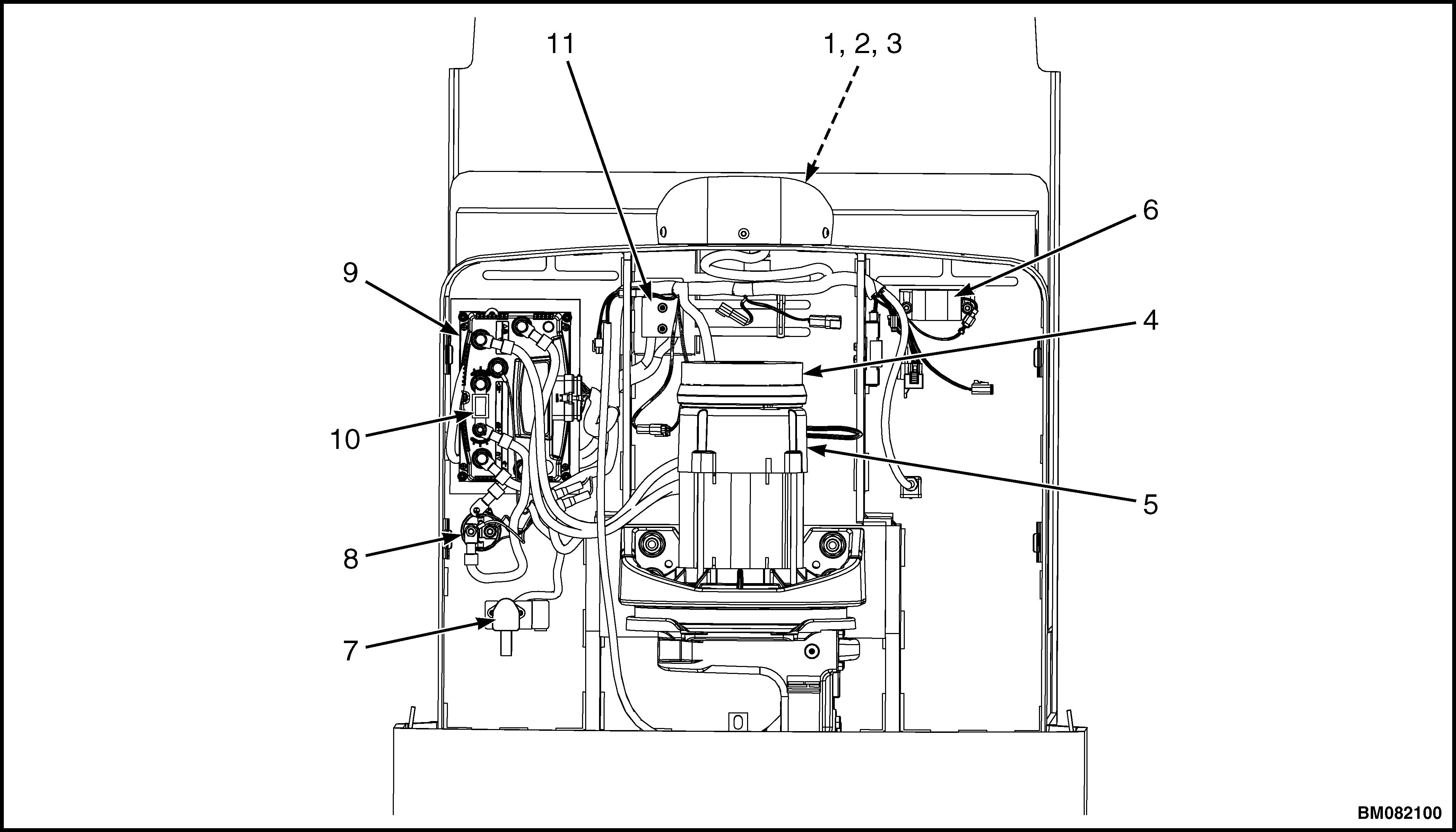
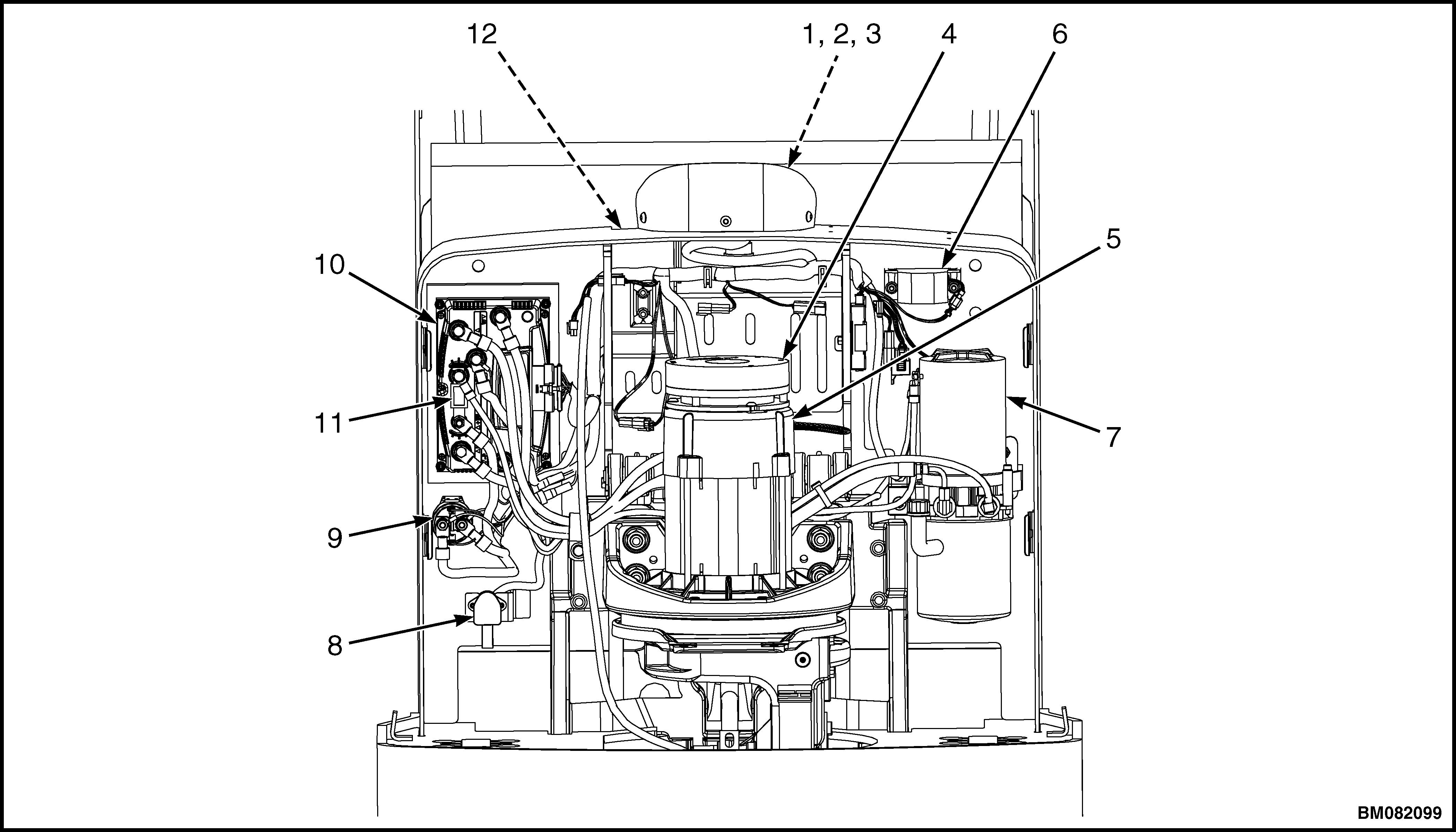
1. KEY SWITCH 2. BATTERY DISCHARGE INDICATOR (BDI) 3. PARKING BRAKE SWITCH 4. PARKING BRAKE 5. TRACTION MOTOR 6. HORN 7. DIAGNOSTIC CONNECTOR 8. CONTACTOR 9. CONTROLLER 10. FUSE 11. BATTERY CONNECTOR