3 minute read
THROTTLE POSITION SENSOR (TPS)

from Hyster G005 (H3.50XL H4.00XL-5 H4.00XL-6 H4.50XL H5.00XL) Forklift Service Repair Manual
by amanda

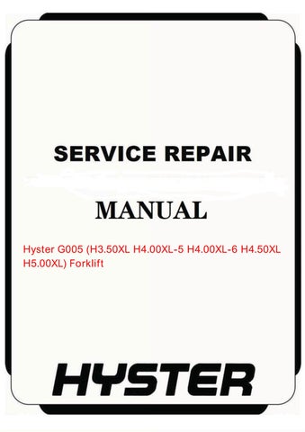
KEY (PART NO. 1338734) SHOWN IN ACTUAL SIZE
A = GROUND B = DIAGNOSTIC
Advertisement
TERMINAL E = SERIAL DATA FOR
SCAN TOOL
AB E
TERMINAL IDENTIFICATION
FIGURE 4. KEY FOR ALDL CONNECTOR
When the ignition switch is “ON” and the engine is stopped, the “Check Engine” light will illuminate in a slow sequence to indicate a “Code 12”. A Code 12 is indicated by “one flash” of light followed by a pause and then “two flashes” to indicate that the fault monitor system is operating. A Code 12 only indicates that the fault monitor system is operating. The fault monitor system will repeat a Code 12 twice and then send another code sequence if there is a fault. If there are no other fault codes stored in the ECM, a series of two Code 12 sequences will continue to repeat as long as the key is in the ALDL connector and the ignition switch is turned to “ON”.
NOTE: The code sequence occurs slowly at a rate of approximately one “flash” per second. Service people must wait long enough to make sure they have the complete and correct code sequences before beginning troubleshooting.
If the ECM has a fault stored in its memory, another code sequence will “flash” after the series of two Code 12 sequences. More than one fault code can be stored in the memory of the ECM. The ECM will send a Code 12 and then the fault codes beginning with the lowest number fault code first. The code sequences will continue to repeat as long as the key is in the ALDL connector and the ignition switch is “ON”. The identification of the code sequences are shown in FIGURE 5. The normal operating conditions of each sensor are stored in the ECM. When a sensor indication is not within the normal operating conditions, the ECM will illuminate the “Check Engine” light on the instrument panel. The code indicates the circuit that has the problem. If Terminal “B” is connected to Terminal “A” when the engine is running, the “Check Engine” light will indicate a code if the fuel system is not operating correctly. A code that is not regular nor constant is a code that occurs and then does not repeat when the code is cleared during troubleshooting. This type of code is most often caused by a loose connection. The schematic diagram of the circuit and the troubleshooting suggestions are useful in finding this type of problem. A “hard” code is a code that continues to indicate a problem while you are working on the lift truck. The code Chart for the code indicated by the ECM will help find the problem.
How To Clear A Code
CAUTION DO NOT damage the ECM! The ignition switch MUST be “OFF” before battery voltage is disconnected. Do not disconnect a power cable, fuse, or jumper cable that supplies power to the ECM until the ignition switch is “OFF”.
When the ECM senses a problem and sets a code in memory, the “Check Engine” light will illuminate. If the problem is not constant or not regular, the “Check Engine” light will go dark 10 seconds after the fault has stopped. The fault code will stay in the ECM memory until the engine has been started 50 times or the battery voltage has been removed from the ECM. If the battery voltage is removed from the ECM for 30 seconds, all codes in memory will go away. Remove any problem codes from the ECM memory after repairs have been completed. Also, some of the troubleshooting charts will indicate to remove the current codes before using the troubleshooting chart. This procedure permits the ECM to set the code while troubleshooting and can help find the problem more quickly.
Fault In The ECM (See CODE 51 on page 46)
Begin troubleshooting at the “SYSTEM CHECK” described in FIGURE 2. The code system indicates a prob-