38 | SAFETY
New rules Jim Phillips, PE, founder of Brainfiller.com, associate director of Electrical Safety UK Ltd and Vice-Chair of IEEE 1584 discusses what’s changed in the 2018 Edition of IEEE 1584
T
he Greek Philosopher Heraclitus is credited with the phrase “The only thing that is constant is change.” That is certainly the case with the new 2018 Edition of IEEE 1584 ‘IEEE Guide for Performing Arc-Flash Hazard Calculations’. Almost everything has changed – except the title! The first edition of IEEE 1584 was published on September 23, 2002. Based on over 300 arc flash tests (considered a lot back in its day) it contained empirically derived equations for calculating the arcing short circuit current, incident energy and arc flash boundary. Since it was first introduced back in 2002, IEEE 1584 has gained widespread global use for performing arc flash risk assessments.
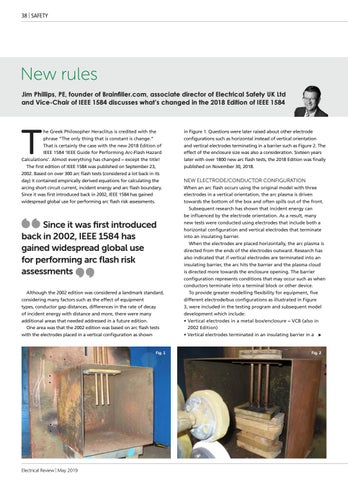
Since it was first introduced back in 2002, IEEE 1584 has gained widespread global use for performing arc flash risk assessments Although the 2002 edition was considered a landmark standard, considering many factors such as the effect of equipment types, conductor gap distances, differences in the rate of decay of incident energy with distance and more, there were many additional areas that needed addressed in a future edition. One area was that the 2002 edition was based on arc flash tests with the electrodes placed in a vertical configuration as shown
Fig. 1
Electrical Review | May 2019
in Figure 1. Questions were later raised about other electrode configurations such as horizontal instead of vertical orientation and vertical electrodes terminating in a barrier such as Figure 2. The effect of the enclosure size was also a consideration. Sixteen years later with over 1800 new arc flash tests, the 2018 Edition was finally published on November 30, 2018.
NEW ELECTRODE/CONDUCTOR CONFIGURATION When an arc flash occurs using the original model with three electrodes in a vertical orientation, the arc plasma is driven towards the bottom of the box and often spills out of the front. Subsequent research has shown that incident energy can be influenced by the electrode orientation. As a result, many new tests were conducted using electrodes that include both a horizontal configuration and vertical electrodes that terminate into an insulating barrier. When the electrodes are placed horizontally, the arc plasma is directed from the ends of the electrodes outward. Research has also indicated that if vertical electrodes are terminated into an insulating barrier, the arc hits the barrier and the plasma cloud is directed more towards the enclosure opening. The barrier configuration represents conditions that may occur such as when conductors terminate into a terminal block or other device. To provide greater modelling flexibility for equipment, five different electrode/bus configurations as illustrated in Figure 3, were included in the testing program and subsequent model development which include: •V ertical electrodes in a metal box/enclosure – VCB (also in 2002 Edition) • Vertical electrodes terminated in an insulating barrier in a
Fig. 2