16 minute read
Gossage: Gossip

GOSSAGE
“No true friends in politics”
Advertisement
In my December diary I pointed out that there might be problems ahead for the woman who had been appointed in the summer by Prime Minister Johnson to be president of the big fortnight-long multinational climate change conference, due to be held in Glasgow this November. I warned that Claire Perry O’Neill might not survive in post to complete the job. How prescient my warnings are proving to be. I expressed concern that all her predecessors running these annual “Conference of the Parties” events had invariably been either heads of, or at minimum senior ministers in, the host government. I reported that our co-hosts, the Italian government, were already offended that somebody who was no longer a Member of Parliament, let alone a senior minister, had been nominated. I mused that their anger might be abated were Claire to become a Baroness. After all, everybody loves a Lady. But the New Year’s Honours List did not contain her name. Instead she received a Friday night telephone call from Johnson’s Rasputin, the odious Dominic Cummings. He told her she had been fired, apparently because she wasn’t a trained diplomat – an omission of which Johnson presumably was aware when he had appointed her. No replacement was named. Just before, the former Conference President had warned in a BBC interview that there would be just “one shot” of success at this conference. If it failed, “it could mark the end of the global approach to tackling the problem of climate change”. We have been warned.
Another fallout from Brexit. The island of Ireland as a whole is heavily reliant on energy from Great Britain. The Republic and the North have constituted one single energy market ever since the 1998 Good Friday Agreement. This market constitutes an energy island save for just two underwater power links, both of which go to Great Britain. Most of Ireland’s oil and gas imports come from the UK. There is no prospect of gas or electricity ceasing flowing between the UK and Ireland, because energy trading isn’t something that depends on EU membership. But the EU does govern the rules and standards around such flows, and that’s what is causing concern in Dublin. For instance, if the British government really does deliver on its threats to diverge on energy usage standards, it could get a lot harder to trade energy between them. It may also become difficult to address short-term shortages if the energy regulators are not cooperating as they used to through EU bodies. Complications would also arise if disputes between the two regulators emerge, because given the UK’s obduracy, those disputes could no longer be resolved by the European Court of Justice.
Because of this, state-owned utility EirGrid has pressed the European Commission for EU funding for a planned €930 million underwater electricity link across the Celtic Sea to France. This would enhance European energy connections: the project is a joint venture between EirGrid and French utility RTE. “It’s a project of common interest and a project of enormous strategic importance to an island nation which post-Brexit, is not connected to Europe,” warns EirGrid CEO Mark Foley. Quite so.
Back to the future
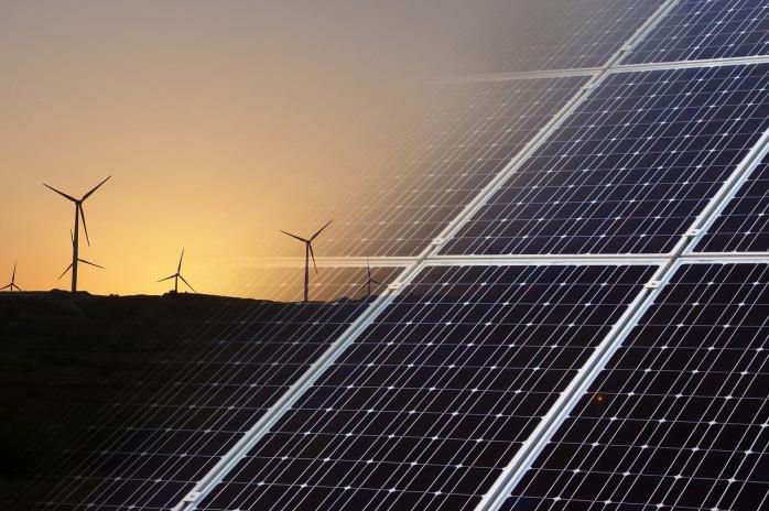
Pause for thought for those convinced that achieving net zero carbon means electric heating will become the norm in all British buildings within the next 15 years. Currently over 80% of UK homes depend on gas for heating and cooking. For so long as gas produces greenhouse gases like carbon dioxide and methane, its days must be numbered. But what if gas production could become as it was before North Sea Gas, when town gas was made available to homes that was more than 50% hydrogen, after being derived from coal? Presently hydrogen is mostly produced for commercial use by extracting it from natural gas, which is carbon intensive. But technically it is equally easy to extract hydrogen from freshwater or seawater using electrolysis – a process that involves passing an electric current through water to obtain hydrogen and oxygen. When the hydrogen is burned it produces only water as waste, and no carbon dioxide. Several trials are already taking place in the UK with existing gas distribution networks to supply homes with a mixture of up to 20% of hydrogen and natural gas. Others are developing networks that can burn 100% hydrogen. However, current legislation bans more than 0.1% of hydrogen in the gas network. If either or both of these trials prove successful, the government will have to change legislation to allow such schemes to be rolled out to consumers, thus retaining the gas network of transmission and boilers.
Given the right regulations and market incentives, around 60% of the heat supplied to domestic, commercial and industry consumers could come from hydrogen in the gas network. Sales of gas to buildings (its main market) have already dropped by one-third since 2005, thanks to better energy efficiency. It is reckoned that more insulation and modern glazing could easily reduce gas use by a further quarter by 2035. The future may not be quite as electric as many are naively assuming.

Heating up history
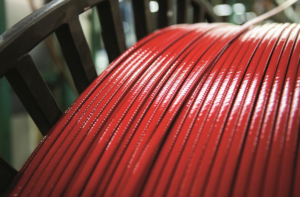
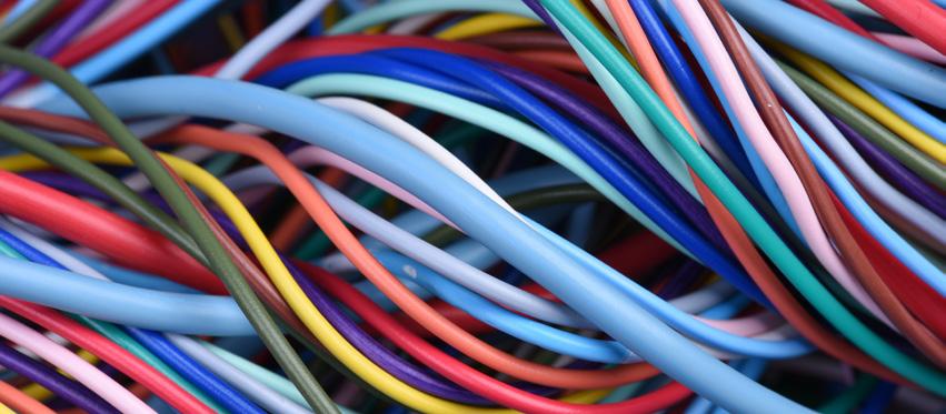
Koen Verleyen, marketing manager at nVent, explores the rise of heat tracing cable technology.
eat tracing technology has become an essential addition to H many industries, used widely to protect pipes and surfaces from freezing, and to maintain fluids at the right temperature for processing or storage. The technology, which has been finessed over several decades, works by applying heat to a pipeline or vessel to replace heat loss through thermal insulation to the ambient environment.
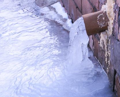
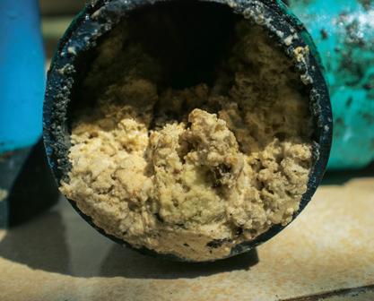
It’s a growing area; the electrical heat tracing market is expected to be worth US$3.26 billion by 2023. Today, the technology is commonly used in commercial and residential properties, to protect water lines, such as fire sprinklers and wastewater, from freezing. Its use also extends to roofs and walkways, to help maintain the process temperature of fluids, for example grease waste slips in factories and restaurants. The oil and gas industry, too, has come to rely on heat tracing technology to keep offshore vessels and platforms running safely and smoothly in freezing conditions.
Steam: The very beginning Before the use of cables, steam was used as a traditional heat tracing system as early as the 1900s, due to its high heat capacity and suitable heat transfer coefficient. It works by dissipating its latent heat to the process pipe, to compensate for the loss in heat, enabling it to maintain a constant temperature. These benefits mean steam is still frequently used today, often in power industries, where it is already a ‘free’ by-product of the core process.
However, there are challenges to using steam. It can waste high amounts of energy, as more heat is provided to the system than is needed to maintain design conditions. It is also difficult to control the pipeline temperature and energy usage, which can lead to health and safety issues. Crucially, steam tracing systems can be costly to install and require regular maintenance to prevent leaks, corrosion or blocked steam traps.
Innovation in electricity The development of electric heat tracing began in the 1930s, as a result of innovative chemical and electrical experimentation. With a unique composition of copper wires, packed in a sheath alongside powdered materials, such as magnesium oxide, mineral insulated cables were a viable alternative to steam, ensuring low flammability, even when used in extreme temperatures and conditions.
They were prone to fail at termination points in the presence of fire or moisture, and were unsuitable for use with heavy machinery as they could crack. Additionally, the magnesium oxide insulation was hygroscopic, causing the cables to draw in moisture and potentially cause electrical leakage. Early controllers were rudimentary and opportunistically adapted from other equipment. This carried some safety risks, as well as low accuracy levels.
Raising the bar with resistance The 1950s saw a more specialised mineral insulated resistance heating cable enter the market. Conductors were constructed from high-resistance alloy, which made them more specialised, and therefore, more effective than their previous counterparts. This was a huge step for industries, such as oil and gas, which needed a solution for applications with high exposure temperatures, or with a high-power output. This development
also helped to meet the need for specific temperature conditions in bitumen production and liquid salt in concentrated solar power (CSP) plants, as well as preventing condensation in incinerators.
Despite progress in this area, overheating and energy inefficiency continued to be a problem – particularly for many high-risk assets. Since they still contained magnesium oxide insulation, they needed to be designed carefully off-site to prevent electrical leakage. This made any on-site repairs or installations with last-minute changes challenging. Due to the intricate nature of the cables, they could also not be overlapped, leading to issues during complex piping installations.
Experimenting with heaters Continuing with innovation in the area, specialised heaters for longline pipelines arrived in the 1960s. These worked by placing a current carrying conductor, energised at a high voltage inside a ferromagnetic tube, to allow a small current to be induced via magnetic inductance, causing resistive heating in the tube. This is known as ‘skin-effect’ heating and is limited to long runs of unbranched pipe work, between 1-15 miles (1.5-25 km).
As such, these heaters needed careful planning for the design of the transformers and equipment to ensure the required level of heating. Demand was therefore still growing for an effective solution that would suit smaller circuits as well.
Hitting a milestone Through experimentation over the years, Raychem Corporation (now a part of nVent) developed the first conductive polymer self-regulating heat tracing cable in 1972. With polymer-based cables constructed from crosslinked polymers, a conductive path was created between conductors. In cold pipes, the core or fibre contracts microscopically, to open electrical paths and increase the current. In warms pipes, expansion disrupts electrical paths to lower the flow of current.
The introduction of self-regulating heating cables was a significant development, as power output could be more effectively regulated for the first time. Being able to control the temperature of pipework on a micro scale was crucial to overcome the overheating problem, in addition to lowering general energy costs. The wattage is also not affected by its length, enabling the self-regulating cables to be cut to length on-site —
helping to save time and energy.
Since this development, electric heat tracing technology has expanded to provide solutions for much broader applications, including roof de-icing, embedded snow melting, floor heating, window condensation prevention and marine applications. Globally, it has proved beneficial for use in harsh geographical conditions, such as the arctic and Middle East, as well as for specialised applications like sulphur transfer, crude oil transport, asphalt lines and oil well heating.
Keeping it constant Building on the success of self-regulating technology, constant wattage zone heaters have since been developed as a cost-effective alternative to mineral insulated cables. Their design is based on a constant wattage alloy, which is helically wound around an insulating core, shortening the deployed length of resistance wire. It is then wrapped around two insulated parallel bus wires, with alternating nodes at regular intervals, to create zones between 3-6 ft (1–2 m).
This functionality allows cables to be cut to length to suit varied wattage applications in the field, enabling heaters to be overlapped once. Constant wattage heaters are also are well suited to higher temperatures and as such, hazardous conditions.
Where next? As the world is becoming increasingly digitised, the demand for more intelligent, responsive systems will drive further innovation in the industry. Taking advantage of smart technology and the Internet of Things (IoT), the latest heat tracing systems will be much more intuitive and able to be integrated into a smart device management network, allowing for unprecedented levels of insight and control — even in large, complex systems.
Size matters
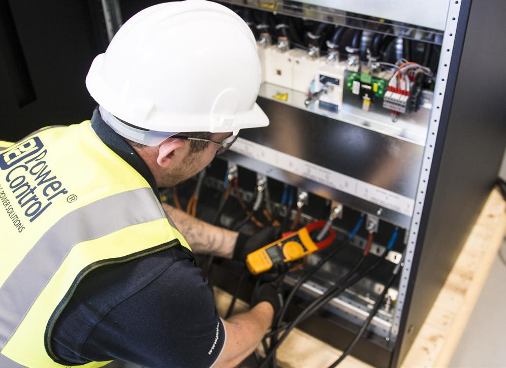
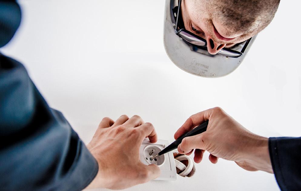
Rob Mather, solutions director at Power Control, discusses the often controversial topic of sizing DC cables and DC isolation.
There’s no question that DC isolation is a means of preventing a direct current (DC) from transferring between two parts of a system while still allowing signal and power to transfer the parts. However, with so many isolation methods, there are questions about which one is best.
As stipulated in both the International Electrotechnical Commission (IEC) and the UK IET (BS 7671:2008), the Safe Extra-low voltage (SELV) of a direct current cannot exceed 120V DC. The guidance on how this is to be achieved is often interpreted differently. Some companies construe this to mean that the batteries must be separated to be under 120V (typically eight batteries) before deemed safe for an engineer to work on them. Naturally, the problem with batteries is that they are always live, so isolating them from a power source within a three phase UPS system, which will typically use between 30 and 60 batteries, is not achievable.
Whilst separating eight of the batteries is perhaps the safest method of DC isolation to comply with regulations, it is far from being cost effective. The batteries in each set of eight will require cabling back to a breaker, and then to the next battery in the string with the connecting links being added afterwards. In order to accommodate this, the DC isolators need to be much more complex. Connecting the end links on a battery string last, and the layout of the batteries in a cabinet or rack, should make it very difficult to cause a short circuit in error, and therefore be in compliance with these standards. Ensuring that all battery terminals have shrouds to prevent any exposed terminals is also required.
If you sell products or work on projects within Power, Lighting, Fire Safety & Security, Energy Efficiency and Data Centres, make sure you enter:


ENTRIES CLOSE SOON visit awards.electricalreview.co.uk


Your business and your team could be celebrating in the spotlight at the ER & DCR Excellence Awards Gala Dinner on 21 May 2020


at the breathtaking Christ Church, Spitalfi elds in London!
Sponsors:


Sizing a DC cable also causes conflicting opinions with companies forming their own interpretation of requirements.
Following compliance guidance from the NICEIC, at Power Control, we believe the DC cable should be sized to the maximum requirement of
a UPS in a worst-case scenario. When using this approach, the regulations also specify that the cable’s maximum temperature rating needs to be considered.
In reality, the maximum demand from the UPS will only be in effect for a short period of time – most battery autonomies are designed at ten minutes. The difference in current between a fully charged battery and a battery near full discharge can be 25%. In addition to this, the fact that a majority of UPS systems are never operated at full capacity makes it clear to see why some suppliers may take a risk and undersize DC cabling to be more competitive on price or to simply increase their margin.
DC breakers and fuse ratings are much of a likeness, both remove electrical power from an electrical circuit. For example, if a 200kVA UPS requires 400A DC isolation to match the maximum demand, the chances of the breaker or fuses tripping on overload are almost non-existent. This is because the battery voltage will have collapsed and therefore the inverter will have turned off long before the breaker or fuses will have tripped – typically they have 20% overload for 30 minutes. The only real protection is offered if the DC cable between the batteries and the UPS is damaged to create a direct short circuit (the UPS DC fuses will also fail) and this is essential protection. DC isolation will prevent the UPS from having an internal short circuit; however, by their very nature, batteries cannot be isolated in this scenario and a battery short circuit may not be avoidable.
When configuring a battery design that requires multiple strings, varying methods of achieving a required autonomy should also be considered. Such as, if there is a need for all of the batteries to be connected when a minimum autonomy of five minutes is desired, then all battery strings will usually need to be connected at the same time. However, if a ten-minute autonomy is needed, the battery set may be configured in such a manner to allow one string to be isolated for maintenance purposes. This would mean a level of redundancy would be built in without too many extra costs.
UPS suppliers should aim to allow for this in battery configurations whenever possible to make ongoing O&M much more manageable in the event of any work needed on the batteries during the lifetime of the UPS. A UPS operating at a reduced battery autonomy is preferable to one operating with no effective autonomy.
The method used to isolate batteries on a multiple string system is dependent on the supplier. A lot of suppliers will have a main DC breaker or isolator and then individual string fusing, this is a perfectly acceptable method. The problem occurs further down the line when a single string needs isolating. The standard fuses are there for protection, not isolation
when a voltage passes through them. Consequentially the whole battery set firstly needs isolating and then the fuses removing on the individual string before the rest of the batteries are reconnected.
I personally prefer individual string isolators to ease the maintenance process and allow any individual string to be isolated without affecting others. Where there is a concern of having to switch multiple isolators to remove electrical power from the batteries in an emergency situation, a DC breaker can be used with a shunt tip function and these can all be connected to a master emergency power off (EPO) switch.