Signal & Image Processing : An International Journal (SIPIJ) Vol.7, No.1, February 2016
NIRS-BASED CORTICAL ACTIVATION ANALYSIS BY TEMPORAL CROSS CORRELATION Raul Fernandez-Rojas1, Xu Huang1, and Jehu Lopez-Aparicio2 1
Faculty of Education, Science, Technology and Mathematics, University of Canberra, Australia 2 Faculty of Sciences, National Autonomous University of Mexico, Mexico
ABSTRACT In this study we present a method of signal processing to determine dominant channels in near infrared spectroscopy (NIRS). To compare measuring channels and identify delays between them, cross correlation is computed. Furthermore, to find out possible dominant channels, a visual inspection was performed. The outcomes demonstrated that the visual inspection exhibited evoked-related activations in the primary somatosensory cortex (S1) after stimulation which is consistent with comparable studies and the cross correlation study discovered dominant channels on both cerebral hemispheres. The analysis also showed a relationship between dominant channels and adjacent channels. For that reason, our results present a new method to identify dominant regions in the cerebral cortex using near-infrared spectroscopy. These findings have also implications in the decrease of channels by eliminating irrelevant channels for the experiment.
KEYWORDS Signal processing, functional response, cortical activation, medical imaging analysis, fNIRS.
1. INTRODUCTION Functional Near-infrared spectroscopy (fNIRS) is a non-invasive optical topography technique that enables continuous monitoring of local hemodynamic and oxygenation response associated with activated areas in the brain cortex. fNIRS has been applied in studies to assess cerebral functioning such as tasks on motor skills [1], auditory stimulation in newborn infants [2] , processing of faces [3, 4] and language skills development in infants [5, 6], or perception of pain [7, 8]. However, the large number of channels (24, 48, or 52) used to quantify simultaneously the brain activity in patients makes the analysis and post processing of brain signals a demanding task. For that reason, region of interest (ROI) of NIRS signals are of high importance. Region of interest are defined as a specific area (anatomical location) on a digital image that is designated to implement further examination. ROIs are of common use in medical imaging techniques such as in functional magnetic resonance imaging (fMRI) where activated regions are of particular interest. ROIs are defined on the hypothesis that the information is retained in activity patters among groups of neurons [9] and that through different patients there are regions in the human brain that exhibit the same functionality [10]. Poldrack [11] presents three reasons to choose specific regions for further analysis: a) to detect activity patterns across different conditions or variables, b) to decrease the number of statistical tests to control for Type I error, and c) to limit testing to a smaller region that is selected on the basis of functionally specific regions such as retinotopically organized regions in primary visual cortex or motion-sensitive regions in middle temporal cortex. In functional MRI ROIs are defined either in terms of specific DOI : 10.5121/sipij.2016.7104
31
Signal & Image Processing : An International Journal (SIPIJ) Vol.7, No.1, February 2016
structural or functional features [9], however the best practice is to define ROIs for each subject based on their own anatomy [11]. In fNIRS analysis, regions of interest are also of use. The analysis of ROIs can be done through analysis of channels of interest (COI) that show a substantial hemodynamic concentration increase after evoked stimulation compared to the base-line measurement. In the neurosciences field the fluctuations in blood circulation by induced stimulation is also known as “hemodynamic response” [12]. In the literature, there are various methods proposed to obtain region of interest in functional NIRS. Some of the proposed methods are: probabilistic mapping methods[13], principal component analysis (PCA)[6], contrast-to-noise-ratio (CNR)[14], and Cross-correlation analysis[8]. Nevertheless, these approaches do not show the dominant channel, and neither the relationship between the dominant channel and adjacent channels; these two features are important to reduce the number channels for further processing. For these reasons, this study offers a method to identify the dominant channel in each cerebral hemisphere by using a time-dependent cross correlation algorithm. In our experiments, we use a data set of cerebral hemodynamic responses from an acupuncture stimulation test on six subjects [7]. The cross correlation computation of NIRS data exposed the existence of dominant channels, the association with neighbouring channels and the extent of the activated areas in the subjects’ cerebral cortex.
2. MATERIALS AND METHODS 2.1 Acquisition Equipment. Data collection was carried out using the Hitachi ETG-4000 (Hitachi Medical Corporation) to investigate cerebral hemodynamics. This equipment uses near infrared light to monitor hemodynamics in the cerebral cortex. NIR light is transmitted to the patient’s head using multiple optical fibre emitters (Fig. 1, red circles). The emitted NIR light penetrates head tissue and bone to reach the cerebral cortex, which are transparent to light in the NIR region. The NIR light reaches the brain cortex and some NIR light is absorbed by hemoglobin, while the non-absorbed light is reflected to the source where it is sampled by an optical detector (Fig. 1, blue circles). The NIR light between emitters and detectors is sampled at a given time point named channels (Fig. 1, numbered squares). The absorption of NIR light of Oxy-hemoglobin (HbO) and Deoxyhemoglobin (HbR) is done at two different wavelengths of light (695 and 830 nm respectively) for their continuous monitoring. The NIRS equipment also provides the total hemoglobin (HbT) which is calculated as the difference between HbO and HbR.
Figure 1. Channel configuration, right hemisphere (channels 1-12) and left hemisphere (channels 13-24). 32
Signal & Image Processing : An International Journal (SIPIJ) Vol.7, No.1, February 2016
The configuration utilized to complete our stimulation experiment has the following parameters. The sample frequency used was of 10 samples per second. The probe configuration used for this study was using two probes of 12 channels to measure neurologic activity. Fig. 1 shows the 24channel configuration used in the study, channels 1 to 12 represent the right hemisphere, while channels 13 to 24 represent the left hemisphere. The measurement area examined is the bilateral motor cortex area, as we expected to obtain hemodynamic response in the somatosensory cortex area (S1)[15, 16]. The probes were centred on the C3 and C4 position, following the specifications of the international EEG 10-20 system[17].
2.2 Participants and Experimental Procedure In the present study, six volunteers (2 females, 4 males) were examined, participants with an age range of 25 to 35 years (mean age 27.8) old were included. In addition, subjects suffering any medical condition, or with a history of a significant medical disorder, or currently taking any medication, were excluded from the study. Before the initiation of the experiments, each participant provided written consent to take part in the study. All participants were explained about the acupuncture procedure and manipulations, and the subjects had the opportunity to stop the procedure at any time if needed. Additionally, all the subjects reported that never had used any type of acupuncture treatment in the past, and no incidents were reported during and after the acupuncture procedure. As a result of collaborative research between the School of Oral Medicine of Taipei Medical University (TMU, Taiwan) and the University Of Canberra (UC, Australia) the experiments were carefully planned by these two institutions. The study and methods were carried out in accordance with the guidelines of the declaration of Helsinki and approved by full-board review process of the TMU-Joint Institutional Review Board under contract number 201307010. All experiments were carried out at TMU in a quiet, temperature (22-24oC) and humidity (40-50%) controlled laboratory room. The experiments were done in the morning (10:00am-12:00pm) and each experiment lasted around 30 minutes. NIRS data was collected using the ETG-4000, with the patients sat down in an ergonomic chair near the topography system (Fig. 2, left panel). Stimulation-related activation in the cerebral cortex was achieved by acupuncture to induce pain stimulation in a safe manner. Only brand-new acupuncture needles were used for each experiment, and using traditional Chinese acupuncture techniques performed by an acupuncturist of the TMU Hospital. The “Hegu” puncture point was used for stimulation, this acupuncture point is located on top of the hand, between the thumb and forefinger (Fig. 2, right panel). This point was selected because it is an area of easy manipulation and the hand can be set aside while the patient is relaxed on the chair. Each participant was punctured on both hands, each hand on separate days; each hand was treated as a separated experiment [18].
Figure 2. Left image shows a subject wearing the multi-channel probe next to the spectroscopy equipment. Right image presents the acupuncture needle in the “Hegu point”. 33
Signal & Image Processing : An International Journal (SIPIJ) Vol.7, No.1, February 2016
The acupuncture procedure consisted of three types of acupuncture stimulations (tasks). The first stimulation is needle insertion (T1), the following stimulation is needle twirl to increase Qi (T2), which was repeated three times, and the last stimulation is needle removal (T3). Task T1 and T3 lasted 6 seconds, while T2 and after each stimulation a resting time (Rt) of 30 seconds was done. Fig. 3 presents an example of the results obtained in the stimulation experiment. The complete data set was used as primary source to assess our dominant channel identification method. Each acupuncture manipulation was applied within the time indicated by the dot lines (markers) in Fig. 3, four channels were used only for illustration purposes. It is worth mentioning that there is delay in reaction time between the physical stimulation and the NIRS signal among all the stimulations, and this is consistent with previous research using NIRS [19]. T1
T2
T2
T2
T3
0.9
OxyHemoglobin (mM*mm)
0.8 0.7 0.6 0.5 0.4 0.3 0.2
Ch12
0.1
Ch1
0
Ch7 Ch10
-0.1 -0.2
301 361
661 761
1061 1161
1461 1561
1861 1911
Samples (10/sec)
Figure 3. Example of the stimulation response using four channels (Ch1, Ch7, Ch10, Ch12). The acupuncture stimulations tasks (T1-T3) are also presented. Each acupuncture manipulation was applied within the time indicated by the dot lines (markers).
Needle insertion (task 1) was the first acupuncture manipulation in the experiment. Once the insertion was done (within samples 301 and 361), the needle was twirled until de-qi (Chinese for obtaining the qi or arriving at the qi) was reached. Once the patient manifested the numbness/heaviness in the arm, the acupuncturist stopped the stimulation. This de-qi sensation was approximately reached three seconds after needle insertion. It is worth mentioning that in all subjects the highest peak was exhibited after this first stimulus (needle insertion). Needle twirl (task 2) by the acupuncturist and it aims to increase the de-qi sensation. The time frame for this stimulation is ten seconds (samples 661-761) and was carried out immediately after resting time (Rt1). The second (within samples 1061-1161) and third (within samples 1461-1561) twirl stimulation exhibited a different pattern than the first stimulation. These responses were smaller than the first responses. Figure 4 shows 10 samples from subject 4 during the complete experiment at different stages of it. The fact that the hemodynamic response decreased (compared to the first twirl stimulation) can be described by two factors: 1) the patient was familiar with the twirl manipulation and became adapted to this sensation, 2) by applying pressure in the hogu point (well known by its analgesic properties) the patient experienced a painkiller effect that decrease the effect of pain by needle manipulation. After the stimulus application, the patient was given 30 seconds to rest. Hemodinamics of needle removal (task 3) are similar to task 1, in this stage the removal was done within a time frame of five seconds (samples 1861-1911). After needle removal patient was given 40 seconds to rest which was used to let the signals go back to base line and to end the experiment.
34
Signal & Image Processing : An International Journal (SIPIJ) Vol.7, No.1, February 2016
11
08
12 09
03 01
04
06
10
07 05
06 03 01
02
11 08
12 09
10 07
04
05
11
08 01
03
06
09
12 10 07
04
03 01
05
11 06
08
12 09
10 07
04
05 02
02
08 06
03 01 11 08 03 01
04
06
09
12 10 07
08 03
05
11 09 06 04
05
02
11
12 10 07
04 02
01
02 12 10 07
01
24
23
24
23
24
23
24
23
24
23
02
11 08 06
05
03
04
05
03 01
09
11 08
12
06
07
06 04
09
10
08
09
10 07 05 02 12
09
03
22
21
20
22
21
20
22
21
20
22
21
20
22
21
20
01
19
18
19
18
19
18
19
18
19
18
04
17
16
15
10
14
13
17
16
15
17
16
15
17
16
15
17
16
15
07
24
23
14
13
14
13
14
13
14
13
05
22
21
20
24
23
24
23
24
23
24
23
02
17
19
18
22
21
20
22
21
20
22
21
20
22
21
20
C 1
2
3
4
5
6
7
8
9 10
1
0.5
0.5
0.4
0.4
0.3
0.3
0.2 0.1 0 -0.1
Oxy DeOxy Total
-0.2 220
440
660
880 1100 1320 1540 Samples (10/sec)
1760
1980
2200
Hemoglobin (mM*mm)
Hemoglobin (mM*mm)
14 16
19
18
19
18
19
18
19
18
10
9
B
15
17
16
15
17
16
15
17
16
15
17
16
15
8
7
5 13
14
13
14
13
14
13
6
4 14
11
3
13
12
2
02
A1
2
3
4
5
6
7
8
9 10
0.2 0.1 0 -0.1 Oxy DeOxy Total
-0.2 220
440
660
880
1100 1320 Samples (10/sec)
1540
1760
1980
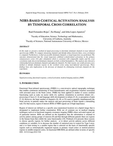
2200
Figure 4. Dynamic haemoglobin response during experiment. A) Ten sequential NIRS images, obtained every 22 seconds, and numbered from 1 to 10. The images show the dynamic change of HbO trough 24 channels. The two images represent each side of the cerebral hemisphere. B) The dynamic trace recorded from channel 1 on the right side of the head. The number along upper Y axis corresponds to the numbered images in A. C) The dynamic trace recorded from channel 17 on the left side of the head. The number along upper Y axis corresponds to the numbered images in A.
2.3 Time-Dependant Cross Correlation In signal processing, cross correlation is used to calculate the temporal similarity between two signals. In our study, the temporal cross correlation is computed to compare NIRS signals and to identify the dominant channels on both hemispheres. The cross correlation function was computed between channels 1-12 in the right probe and 13-24 in the left probe. This measure of temporal similarity of two signals can be done by computing a time-shifting along one of the input signals. The cross correlation between two waveforms x(t) and y(t) can be defined as follows: ∑ . Where is the time-lag between x(t) and y(t), the value of denotes the difference (lag/lead) between channel signal y(t) and channel signal x(t). The cross correlation value between two channels in the same probe is done after each stimulation from -40 sec to +40 sec at a rate of 10 samples per second.
2.4 Visual Evaluation Approach A visual inspection can be done on activation patterns in both hemispheres and will be focus on locating potential dominant areas to evaluate the validity of our study. This visual analysis will be carried out by configuring the NIRS data following the channel configuration shown in Fig 1. This analysis will also show evidence of cortical activity that is associated with the stimulationrelated sensory processing in the cerebral cortex. We observed the responses of Oxyhemoglobin (HbO) on both hemispheres after the evoked stimulation.
35
Signal & Image Processing : An International Journal (SIPIJ) Vol.7, No.1, February 2016
3. RESULTS 3.1 Visual Pattern Identification By using visual inspection, it was possible to depict activated regions in the NIRS data. Fig. 5 shows a colour representation of three images from the right (Ch1-Ch12) and left (Ch13-Ch24) hemispheres of subject four (male, 26 year old). Only needle insertion task (T1) is presented in this study because it was the strongest stimulation reported by all subjects. The images were taken every five seconds after external stimulation, subject and sampling time were chosen for graphic purposes. Two situations were perceived, the existence of a dominant area and the delay in propagation of pain-related activation patterns in the subject cortex. These findings were consistent in all participants and on both hemispheres. I
05
02
A
10
07 04
01
I
12
05
02
09 06
10 07
04 11
01
III 12
02
10
07 04
09 06
05
11
01
12 09
06
11
03
08
03
08
03
08
17
22
17
22
17
22
14
B
II
19 16
13
II 24
16
21 18
15
t1=00:05
23 20
19
14
13
III 24
14 16
21 23
18 15
t2=00:10
20
19
13
24 21
18 15
23 20
t3=00:15
Figure 5. Visual analysis. A) Single dominant pattern. B) Multi-dominant pattern. Three images were taken every five seconds after stimulation. Dotted circles show the dominant region. Cortical activity was initially started in a small region and extended to surrounding areas.
Two types of dominant regions can be seen in our visual analysis; the single-dominant region and the multi-dominant region. Firstly, the single-dominant region is when the dominant area is very evident and stands out compared to other regions. An example of this can be depicted in Fig. 5A, the area around Ch7 (dotted circle) is very evident that this region has a higher response to external stimulus as compared to other areas. Secondly, it is when the data have a multi-dominant response to the external stimulation. Fig. 5B exhibits an example of this case, two regions of interest can be observed; the brain response is greater around Ch19 and Ch18. In this case the selection of a dominant channel is not as clear as the single-region case. In both cases, the selection of a dominant channel is made by visual perception; however in the multi-dominant response, another method is needed to find the dominant channel. After the initial visual analysis, the propagation of the dominant area towards surrounding areas was also eminent. This is evident in Fig. 5A, around Ch7 the magnitude of HbO traces is higher and seems to be the centre of propagation towards adjacent channels in posterior images. For example, in Fig. 5A-I, the area around Ch7 appears to be slightly more active than the rest of the channels. However, after five seconds (Fig. 5A-II) the activation has increased and reached Ch5 36
Signal & Image Processing : An International Journal (SIPIJ) Vol.7, No.1, February 2016
and Ch10. In the last image (Fig. 5A-III), the activation is stronger than previous image and radiation pattern expanded to neighbouring channels Ch2, Ch4, Ch9, and Ch12. This phenomenon suggests a strong relationship between Ch7 and surrounding channels. These activation patterns reflect the increase of HbO in the cerebral cortex. These examples show the need of a tool to quantify the dominant channel and the delay between channels. For that reason, our study presents the use of the cross correlation analysis to identify these two factors. It is worth mentioning that this study is the first to show and quantify the dominant channel and the relationship between dominant channels and surrounding channels with in the measuring probes.
3.2 Cross Correlation Signal Analysis Cross correlation analysis was computed to examine the idea that a dominant channel and a relationship among the channels exist. Fig. 6 presents the results of two cross correlation comparisons of two channels, Ch7 (Fig. 6A) and Ch16 (Fig. 6B) on right and left cerebral hemispheres respectively, from subject four after the acupuncture stimulus. This subject was chosen for illustration purposes only. The analysis was carried out by choosing potential dominant channel and comparing it against the remaining channels in that particular head probe.
Figure 6. Cross correlation comparison of dominant channel and surrounding channels from subject four. A) Time-dependant evaluation of Ch7 and neighbouring channels. B) Time-dependant comparison between Ch16 and neighbouring channels.
To detect the dominant channel in dominant regions, a comparison of the lags was performed between potential dominant channel and the rest of the channels. The detection was carried out by correlating the delay times between a possible dominant channel and the rest of channels in that hemisphere. For instance, the cross correlation analysis presented in Fig. 6A confirmed that the region around Ch7 was the leading area. Moreover, Ch5, and Ch10 have no time delay (τ =0.0 sec) with Ch7, which indicates that these three channels are situated over a potential region of interest due to the strong activation after stimulation. Additionally, the cross correlation analysis of the opposite cerebral hemisphere (Fig. 6B) explained the effect of having two dominant regions after our visual examination. In this case, this result showed that Ch16 (τ =0.0 sec) leads the rest of the channels for this particular subject and experiment. It was also found that Ch18 (τ =+0.8 sec) and Ch19 (τ =+0.3 sec) have minimum lags against Ch16, which rejects the idea of having two separate dominant areas with high response to the external stimulation. Therefore, we can say that for subject 4 (n=4), Ch16 is the dominant channel on the left hemisphere. Consequently, it is possible to define the dominant channel as the measuring channel with the fastest response after the evoked stimulation. In 37
Signal & Image Processing : An International Journal (SIPIJ) Vol.7, No.1, February 2016
addition, in most cases within this experiment, the dominant channel is the channel with the strongest HbO response after noxious stimulation. Another relevance of using cross correlation was to understand the connection between dominant channels and surrounding channels. From the colour representation image in Fig.5 from patient four (n=4), Ch7 was identified as leading channel and adjacent channels have a small delay that confirms that NIRS signals transit from leading channels to adjacent channels. Another way at looking at this is Fig. 7, it presents the delays between channels on both hemispheres. We can see in Fig. 7A that the region formed by Ch2, Ch4, Ch5, Ch7, Ch9, Ch10 and C12 has zero delay (Ď„ ≈ 0 sec), while opposite channels Ch1, Ch3, Ch6, Ch8, Ch11 present a bigger delay against Ch7. This spreading behaviour is a strong indication of the connection of NIRS signals between the leading channel and adjacent channels. We can also see that channels (red squares) with small delays or no-delay with dominant channel present a higher activation. On the other hand, channels with larger delays belong to areas with limited activation (blue squares). Similarly, in the left hemisphere this can be observed as showed in Fig. 7B.
Figure 7. Cross correlation signal processing. Propagation time between activated areas (red) and less active channels (blue). A) right hemisphere. B) left hemisphere.
These results indicate that hemodynamic signals have a progressive movement from dominant regions towards peripheral regions. It is also important to note that the results after following stimulations (tasks) remained very similar, however, the lag and lead times between channels were slightly smaller. This situation can be explained by the fact that the first stimulation produced the strongest response in all the acupuncture experiment.
5. DISCUSSION In the present study, we have used cross correlation signal processing to identify dominant channels in functional near-infrared spectroscopy (fNIRS). Cross correlation analysis finds the dominant region based on the lag times (delays) between channels and also provides an estimation of the relationship between channels. The visual assessment also corroborated the propagation effect and dominant patterns in the NIRS data. First, we used visual inspection of the stimulation-related activation patterns in the brain cortex to obtain an initial assessment of dominant channels. It was expected to obtain activation in functional areas where the cortical representation of pain is involved. It was noted that the brain response increased around the area of channel 7 (Ch7) on the right hemisphere and the area of channel 19 (Ch19) on the left hemisphere in all the subjects. These two areas around Ch7 and 38
Signal & Image Processing : An International Journal (SIPIJ) Vol.7, No.1, February 2016
Ch19 are part of the postcentral gyrus in the parietal lobe. The postcentral gyrus is well known to be the location of the primary somatosensory cortex (S1), area that has been reported to be involved with the perception and modulation of painful somatosensory sensations[16]. It is also important to note that the cortical activation following the acupuncture stimulation was obtained on both hemispheres (bilateral S1 activation). These findings are consistent with previous results [16, 20, 21]. However, other studies in pain stimulation have reported that pain activation can be also detected in the secondary somatosensory cortex (S2), anterior cingulate cortex (ACC), and insular cortex (IC)[15, 22, 23]. Based on this preliminary analysis, we expected to find our region of interest around these areas and also confirmed the validity of our overall acupuncture experiment. Secondly, cross correlation analysis between channels was computed to detect dominant channels as well as the relationship among channels. The cross correlation computation revealed the existence of delays between channels, not only in the ROI but also in the whole measuring probe. These lags between channels represent that leading signals are dominant channels and based on the lag times between channels we can stablish that the delays represent the transition of dominant channels to surrounding areas. Moreover, our results showed that the dominant channel is one of the channels with the strongest response to evoked stimulation. Finally, an important result from the cross correlation analysis is that the number of control signals can be reduced by eliminating irrelevant channels. For example, channels with very small activation after stimulus can be excluded from the data base since they fail to represent any interaction within the experiment. Therefore, signal processing techniques such as cross correlation are of importance to find relevant channels that truly represent activations after stimulus.
6. CONCLUSIONS In conclusion, this study presents the cross correlation signal processing analysis of near infrared spectroscopy (NIRS) signals. The results exhibited the dominant channels in the region of interest on both cerebral hemispheres. This leading channel was seen as the channel with the fastest answer to evoked stimuli; in most of the participants, this leading channel was the channel with the highest activation response after the external stimulation. The results also indicated that the delays of NIRS hemoglobin signals can be seen as a relationship between dominant channel and adjacent channels; these delays can be seen as the delay of localized cerebral blood flow from dominant areas traveling to surrounding areas. In addition, after a visual inspection, it was found that the acupuncture manipulation resulted in bilateral reaction in the primary somatosensory region (S1) in all subjects. In addition, our analysis can be used to reduce the number of channels, since non-active channels can be drop from the analysis; this can help to reduce the analysis complexity. Based on the evaluations, our analysis effectively showed the region of interests and visualizes them as the apparent motion of cortical activity from dominant channel. Consequently, our results present a new method to detect region of interest in functional near-infrared spectroscopy.
REFERENCES [1]
M. Hatakenaka, I. Miyai, M. Mihara, S. Sakoda, and K. Kubota, "Frontal regions involved in learning of motor skill—a functional NIRS study," Neuroimage, vol. 34, pp. 109-116, 2007.
[2]
K. Sakatani, S. Chen, W. Lichty, H. Zuo, and Y.-p. Wang, "Cerebral blood oxygenation changes induced by auditory stimulation in newborn infants measured by near infrared spectroscopy," Early human development, vol. 55, pp. 229-236, 1999. 39
Signal & Image Processing : An International Journal (SIPIJ) Vol.7, No.1, February 2016 [3]
M. Kobayashi, Y. Otsuka, E. Nakato, S. Kanazawa, M. K. Yamaguchi, and R. Kakigi, "Do infants represent the face in a viewpoint-invariant manner? Neural adaptation study as measured by nearinfrared spectroscopy," Frontiers in Human Neuroscience, vol. 5, 2011.
[4]
Y. Honda, E. Nakato, Y. Otsuka, S. Kanazawa, S. Kojima, M. K. Yamaguchi, et al., "How do infants perceive scrambled face?: A near-infrared spectroscopic study," Brain Research, vol. 1308, pp. 137146, 2010.
[5]
J. Gervain, F. Macagno, S. Cogoi, M. Peña, and J. Mehler, "The neonate brain detects speech structure," Proceedings of the National Academy of Sciences, USA, vol. 105, pp. 14222-14227, 2008.
[6]
I. Kovelman, M. H. Shalinsky, M. S. Berens, and L.-A. Petitto, "Shining new light on the brain's “bilingual signature”: a functional Near Infrared Spectroscopy investigation of semantic processing," Neuroimage, vol. 39, pp. 1457-1471, 2008.
[7]
M. Bartocci, L. L. Bergqvist, H. Lagercrantz, and K. Anand, "Pain activates cortical areas in the preterm newborn brain," Pain, vol. 122, pp. 109-117, 2006.
[8]
C.-H. Lee, T. Sugiyama, A. Kataoka, A. Kudo, F. Fujino, Y.-W. Chen, et al., "Analysis for distinctive activation patterns of pain and itchy in the human brain cortex measured using near infrared spectroscopy (NIRS)," PloS One, vol. 8, p. e75360, 2013.
[9]
J. A. Etzel, V. Gazzola, and C. Keysers, "An introduction to anatomical ROI-based fMRI classification analysis," Brain Research, vol. 1282, pp. 114-125, 2009.
[10] A. Nieto-Castanon, S. S. Ghosh, J. A. Tourville, and F. H. Guenther, "Region of interest based analysis of functional imaging data," Neuroimage, vol. 19, pp. 1303-1316, 2003. [11] R. A. Poldrack, "Region of interest analysis for fMRI," Social Cognitive and Affective Neuroscience, vol. 2, pp. 67-70, 2007. [12] E. Ortiz, "Use of Neuroimaging to Clarify How Human Brains Perform Mental Calculations," Online Submission, 2010. [13] M. Verner, M. J. Herrmann, S. J. Troche, C. M. Roebers, and T. H. Rammsayer, "Cortical oxygen consumption in mental arithmetic as a function of task difficulty: a near-infrared spectroscopy approach," Frontiers in Human Neuroscience, vol. 7, 2013. [14] X. Song, B. W. Pogue, S. Jiang, M. M. Doyley, H. Dehghani, T. D. Tosteson, et al., "Automated region detection based on the contrast-to-noise ratio in near-infrared tomography," Applied Optics, vol. 43, pp. 1053-1062, 2004. [15] R. K. Hofbauer, P. Rainville, G. H. Duncan, and M. C. Bushnell, "Cortical representation of the sensory dimension of pain," Journal of Neurophysiology, vol. 86, pp. 402-411, 2001. [16] M. Bushnell, G. Duncan, R. Hofbauer, B. Ha, J.-I. Chen, and B. Carrier, "Pain perception: is there a role for primary somatosensory cortex?," Proceedings of the National Academy of Sciences, USA, vol. 96, pp. 7705-7709, 1999. [17] R. W. Homan, J. Herman, and P. Purdy, "Cerebral location of international 10–20 system electrode placement," Electroencephalography and Clinical Neurophysiology, vol. 66, pp. 376-382, 1987. [18] R. Fernandez Rojas, X. Huang, K. L. Ou, D. Tran, and S. M. R. Islam, "Analysis of pain hemodynamic response using near-infrared spsctroscopy (NIRS)," International Journal of Multimedia and its Applications, vol. 7, pp. 31-42, 2015.
40
Signal & Image Processing : An International Journal (SIPIJ) Vol.7, No.1, February 2016 [19] S. Boden, H. Obrig, C. KĂśhncke, H. Benav, S. Koch, and J. Steinbrink, "The oxygenation response to functional stimulation: is there a physiological meaning to the lag between parameters?," Neuroimage, vol. 36, pp. 100-107, 2007. [20] M. T. Sutherland and A. C. Tang, "Reliable detection of bilateral activation in human primary somatosensory cortex by unilateral median nerve stimulation," Neuroimage, vol. 33, pp. 1042-1054, 2006. [21] M. A. YĂźcel, C. M. Aasted, M. P. Petkov, D. Borsook, D. A. Boas, and L. Becerra, "Specificity of Hemodynamic Brain Responses to Painful Stimuli: A functional near-infrared spectroscopy study," Scientific Reports, vol. 5, 2015. [22] R. C. Coghill, C. N. Sang, J. M. Maisog, and M. J. Iadarola, "Pain intensity processing within the human brain: a bilateral, distributed mechanism," Journal of Neurophysiology, vol. 82, pp. 19341943, 1999. [23] A. V. Apkarian, M. C. Bushnell, R. D. Treede, and J. K. Zubieta, "Human brain mechanisms of pain perception and regulation in health and disease," European Journal of Pain (London, England), vol. 9, pp. 463-463, 2005.
41