https://doi.org/10.22214/ijraset.2023.54929

11 VII July 2023
ISSN: 2321-9653; IC Value: 45.98; SJ Impact Factor: 7.538

Volume 11 Issue VII Jul 2023- Available at www.ijraset.com
https://doi.org/10.22214/ijraset.2023.54929
ISSN: 2321-9653; IC Value: 45.98; SJ Impact Factor: 7.538
Volume 11 Issue VII Jul 2023- Available at www.ijraset.com
Abstract: This research paper gives insight to the analysis of NACA 1412 airfoil. The airfoil is the two-dimensional cross section of the aircraft’s wing. The aircraft flies due to generation of the lift, this lift is caused by the pressure difference on the upper and lower surface of the airfoil. The pressure on the lower surface is greater than the pressure on upper surface which provides a lift to the airfoil. We are going to see the airfoil’s behaviour in incompressible flow at different angles of attack with constant velocity. In this research, we are going to use the Ansys software to do the analysis. This research is based on the computational fluid dynamics concepts. At the end, we will see how the lift and drag changes at different angles of attack and some graphical results from the research.
Keywords: Airfoil, Ansys, mesh, angle of attack, stall.
When the aircraft is flying, there are four main forces which acts on it, they are, lift, drag, thrust and gravity. Wherever there’s a lift, drag is there. To reduce this drag force and to increase the aircraft’s efficiency the designers use different types of airfoils like symmetrical and unsymmetrical or camber. Before all the software, we had to do all the analysis in the wind tunnels, but now Ansys has taken its position and it’s playing an important role in the aviation industry. Here, we are going to use the Design Modeler to design the airfoil and the respective domain and grid our geometry in the Mesh. Fluent solver makes the important part of the analysis. NACA 1412 is a four-digit airfoil. It is an unsymmetrical or cambered airfoil. National Advisory Committee for Aeronautics first developed these NACA airfoils. In the four digits, the first number denotes the maximum camber in percentage with respect to the chord. Second number indicates the location of the maximum camber which is given in tenth of chord and the percentage of maximum thickness of the airfoil is given by the last two numbers with respect to chord. In NACA 1412, we have camber of 1% which is located at the 40% behind the leading edge of the airfoil and it has maximum thickness of 12%. This paper describes the behaviour of the airfoil at 0, 3, 6, 9 and 12 degrees of angle of attack at the constant velocity and then the values of coefficient of lift and coefficient of drag will be plotted with the help of graphs.
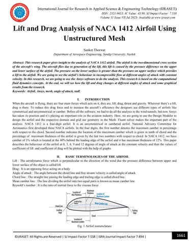
Lift : The aerodynamic force which is perpendicular to the direction of the wind due the pressure difference between upper and lower surface of the object is called lift.
Drag : It is an opposing force acting on a body.
Angle of attack : The angle between the chord line and free stream velocity is called angle of attack.
Chord line : The straight line joining the leading edge and trailing edge is called chord line.
Mean camber line : The line dividing the airfoil into two equal parts is known as mean camber line. Reynold’s number : It is the ratio of inertial force to the viscous force.


ISSN: 2321-9653; IC Value: 45.98; SJ Impact Factor: 7.538
Volume 11 Issue VII Jul 2023- Available at www.ijraset.com
Coefficient of lift : =
where L = Lift, = Air density, = Velocity, = Area of the airfoil
Coefficient of drag : =
where D = Drag, = Air density, = Velocity, = Area of the airfoil

NACA 1412 is an unsymmetrical airfoil with the maximum thickness of 12%. The design of the given airfoil is done in the Ansys Design Modeler. The co-ordinates of the airfoil are imported from the airfoiltools into the Design Modeler. The figures below show the design and the complete Unstructured mesh of the airfoil.


This NACA 1412 airfoil will be tested at different angles of attack i.e., 0, 3, 6, 9 and 12 degrees. In boundary conditions, the inlet velocity is given as 88.653 m/s at constant air temperature of 288.16 K. Here, two equation model k- is used where k is the kinetic energy and is the rate of dissipation of the turbulent kinetic energy. The production of kinetic energy is larger due to large rate of dissipation. The effect of turbulent kinetic energy can be observed by the k- model.

ISSN: 2321-9653; IC Value: 45.98; SJ Impact Factor: 7.538
Volume 11 Issue VII Jul 2023- Available at www.ijraset.com
In the velocity contours, the blue coloured region at the leading edge is the stagnation point at which the velocity of the fluid is almost equal to zero. The upper surface of the airfoil faces the higher velocity than the lower surface. This causes the pressure difference on the both upper and lower surfaces, the pressure on the lower surface is higher than the pressure on the upper surface which creates the lift.


1) At 00 Angle of Attack

ISSN: 2321-9653; IC Value: 45.98; SJ Impact Factor: 7.538


Volume 11 Issue VII Jul 2023- Available at www.ijraset.com
ISSN: 2321-9653; IC Value: 45.98; SJ Impact Factor: 7.538
Volume 11 Issue VII Jul 2023- Available at www.ijraset.com
ISSN: 2321-9653; IC Value: 45.98; SJ Impact Factor: 7.538
Volume 11 Issue VII Jul 2023- Available at www.ijraset.com
As the angle of attack increases, the Cl and Cd values increases. From the figures 5, 6, 7, 8 and 9, it can be seen that the upper surface of the airfoil experiences low pressure and the lower surface experiences high pressure. In case of velocity, the velocity is higher over the airfoil as compared to the bottom of the airfoil. At certain angle the lift suddenly goes down due to the gradually increasing drag and the flow separation. This condition is called stalling and the angle is known as critical angle. This type of airfoil is used in the aircraft’s wing.
[1] John D. Anderson, Fundamentals of Aerodynamics, sixth edition, Mc Graw Hill Education
[2] Vani Sadadiwala “A Detailed Study: CFD Analysis of NACA 0012 at Varying Angles of Attack”, International Journal for Research in Applied Science & Engineering Technology (IJRASET), Volume 9 Issue VII, July 2021
[3] Anagha S Gowda “Comparison of Aerodynamic Performance of NACA 4412 and 2412 using Computational Approach”, International Journal of Engineering Trends and Technology (IJETT), Volume 67 Issue 4, April 2019
[4] H K Versteeg and W Malalasekera, “An Introduction to Computational Fluid Dynamics”, second edition, Pearson Education
[5] S. Kandwal, Dr. S. Singh “Computational Fluid Dynamics Study Of Fluid Flow And Aerodynamic Forces On An Airfoil”, International Journal of Engineering Research & Technology (IJERT), Volume 1 Issue 7, September 2012
[6] R. K. Rajput, Fluid Mechanics and Hydraulic Machines, fifth edition, S. Chand and Company Ltd.
[7] Ira H. Abbott and Albert E. von Doenhoff, Theory of Wing Sections Including a Summary of Airfoil Data, Dover Publications Inc. New York
[8] Airfoiltools [Online]. Available: http://airfoiltools.com/
