wireless communications
figure 1 VCC 2.7V to 6V
C2 100pF
CS 1.2pF 1
Besides having high dynamic range and superior sensitivity, log detectors have excellent bandwidth characteristics.
VCC
RFIN
6
LTC5532EDC 2
VOUT R2 10k
3
VOUT
GND
VM
VOS
RFIN 11.5GHz to 12GHz C1 1.2pF
5
4
R3 10k
A 12 GHz RF Peak Detector Circuit
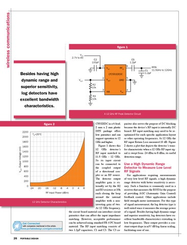
C5532EDC in a 6-lead, 2 mm x 2 mm plastic DFN package offers er exploration 2200 ether your goal TA=25°C low parasitics and can speak directly 2000 support operation to 12 ical page, the 1800 ght resource. GHz and higher. technology, Figure 1 shows this 1600 es and products 12 GHz detector’s 1400 ed RF input matched to 1200 11.5 GHz – 12 GHz. So its input circuit 1000 can be connected to 800 the coupled output 600 of a directional coucompanies providing solutions now pler or an RF source. exploration into products, technologies 400 and companies. Whether your goal is to research the latest datasheet from a company, mp to a company's technical page, the goal of Get Connected is to put you in touch with the right resource. Whichever of Theleveldetector output gy, Get Connected will help200 you connect with the companies and products you are searching for. amplifier gain is exonnected 0 ternally set by the R2 -24 -20 -16 -12 -8 -4 0 4 8 and R3 resistors at 10k RF Input Power (dBm) each closing the loop around the internal amplifier with a non12 GHz Detector Characteristics inverting gain of two. At 12 GHz frequency, the circuit board material can introduce circuit parasitics that can affect the input impedance matching. However, acceptable performance can be achieved using standard FR-4 PC board Get Connected with companies mentioned in this article. material. The RF input matching consists of www.portabledesign.com/getconnected two 1.2pF capacitors, C1 and C3. The C3 ca-
figure 2
VOUT Output Voltage (mV)
nd
End of Article
26
PORTABLE DESIGN
Get Connected with companies mentioned in this article.
pacitor also serves the purpose of DC blocking because the device’s RF input is internally DC biased. RF input matching may need to be reoptimized for each specific application layout or other operating frequencies. At 12 GHz the RF input Return Loss measured 10 dB. Figure 2 shows a plot that depicts the detector’s transfer characteristic when a 12 GHz RF input signal is swept from -24 dBm to 8 dBm, its useful detection range.
Use a High Dynamic Range Detector to Measure Low Level RF Signals
For applications requiring measurements of very low level RF signals, a high dynamic range detector with better sensitivity is necessary. Such a function is commonly used in a receiver that measures the RSSI for the purpose of providing AGC (Automatic Gain Control) feedback control. Other applications include field strength meter instruments. For this type of signal measurement, the log detector type is well suited since it measures the average power of a signal. Besides having high dynamic range and superior sensitivity, log detectors have excellent bandwidth characteristics extending to low frequencies. Their output provides a constant output slope in mV/ dB log-linear scaling, facilitating ease of use.