
A PATCH ANTENNA DESIGN WITH BOOSTED BANDWIDTH FOR ISM BAND APPLICATIONS
Md. Shaharul Islam, Md. Firoz Ahmed, Md. Hasnat Kabir, Md. Ashraful Islamand Md. Matiqul Islam
Department of Information and Communication Engineering, University of Rajshahi, Rajshahi 6205, Bangladesh
ABSTRACT
In recent times, the utilization of microstrip patch antennas (MPAs) has increased due to their simple production, simple analysis, low cost, lightweight, easy feeding, and superior radiation characteristics. Limited bandwidth is a key disadvantage of MPAs. In this paper, a rectangular patch antenna with partial ground plane (PGP) strategy for ISM applications is proposed to overcome this deficiency and its performance is compared with that of a traditional patch antenna. A low-cost FR-4 substrate with a dielectric constant of 4.3 and a thickness of 1.6 mm is used to make both antennas designed. The antennas are analyzed and simulated at the operating frequency of 2.45 GHz using CST software. The simulation results show that the proposed antenna has a 0.1465 GHz i.e. 146 5 MHz bandwidth, which is more than 1.77 times larger than a conventional antenna (bandwidth = 0.0827 GHz i.e. 82.7MHz). The suggested antenna is suitable for a wide range of wireless communication standards, such as Bluetooth (2.4 to 2.485 GHz), WiMAX (2.3 to 2.4 GHz), Microwave ovens (2.4 to 2.48 GHz), RFID (2.4 to 2.5 GHz), S-Band (2.3 to 2.4 GHz), Wireless Communication Services (WCS) 2.345 GHz to 2.360 GHz, and 4G LTE (2.3 to 2.315 GHz).
KEYWORDS
Rectangular Microstrip Patch antenna, Bandwidth Improvement, FR4, ISM
1. INTRODUCTION
The fast growth of wireless communication networks [1] as well as the expansion of remote devices has placed a lot of demand on antenna configurations. Unlike standard microwave antennas, microstrip antennas have a few areas of interest, allowing various applications to cover a broad bandwidth from 100 MHz to 100 GHz. Microstrip antennas can be made in a number of geometric shapes and sizes and are characterized by a variety of properties. A Microstrip Patch Antenna (MPA) is composed of a transmitting patch on one side of a dielectric substrate with either a planar or non-planar shape and a ground plane on the other. In recent years, several different arrangements, including square, annular-ring, circle, rectangle, symmetrical triangular, and dipole have been investigated. These different reception gadgets [2] have a low profile, light weight, reasonably inexpensive manufacturing, thin profile setup, direct and round polarization are achievable with basic feed, and they are easily integrated with microwave coordinated circuits. These antennas offer a large low-power handling capacity, making them suitable for sending and receiving low-power signals. Due to their characteristics, microstrip patch [3 - 4] antennas have potential uses in radar and wireless communication systems. As microstrip patch radio wires offer many benefits, one of their key drawbacks is their extremely slow transmission speed, which is only a few percent, and modest necessary gain.
International Journal on AdHoc Networking Systems (IJANS) Vol. 13, No. 1, January 2023
Numerous strategies [5 - 7] were developed to enhance the impedance bandwidth of microstrip antennas. They have less metalized substrate on the dielectric substrate and less radiation loss than other current systems. Due to restrictions on size, weight, cost, performance, ease of installation, and aerodynamic profile, low-profile antennas may be necessary for highperformance airplane, spacecraft, satellite, and missile applications. The [8] introduced an insetfed antenna using defected ground structure (DGS) to improve the antenna performance. The antenna is especially efficient because of its wide bandwidth and low return loss. A rectangular patch antenna with a novel top-plane switching beam and ground- plane slits was proposed by the authors of [9]. DGS with a circular shape was described in [10]. The authors were able to reduce the antenna size by around 74.5 percent using this method. In [11], the author demonstrated a star-shaped microstrip patch antenna with a microstrip feed line for ISM band. The suggested antenna has an impedance bandwidth of 147.8 MHz and a gain of 2.973 dBi. A rectangular insetfed microstrip patch antenna with and without defected ground structure (DGS) was constructed for ISM band at 2.45 GHz center frequency in [12]. The propounded antenna achieves a bandwidth of 84.8 MHz and a gain of 2.35 dBi. Nowadays, several governments and commercial uses with similar criteria exist, like mobile radio and wireless communications [13]. For these purposes, patch antennas can be used. These antennas have a low profile, are conformable to planar and non-planar surfaces, are simple and inexpensive to manufacture using modern printed circuit technology, are mechanically strong when placed on rigid surfaces, work well with MMIC plans, and are highly adaptable in terms of full recurrence, polarization, example, and impedance when the particular distinct shape and mode are selected. The square, rectangular, and circular are the most often used shapes due to their simplicity in analysis and manufacture as well as their appealing radiation properties, particularly low cross-polarization radiation.
The ISM radio bands [14 - 15] are radio bands (portions of the radio spectrum) allocated globally for the use of radio frequency (RF) energy for industrial, scientific, and medical applications other than telecommunications. Broadcast process heating, microwaves, and medical diathermy machines are examples of previous uses in these categories. Because the high detonations of these components can cause electromagnetic impedance and disrupt radio communication using the same periodicity, they were limited to specified frequency bands. Clients have no administrative safety from ISM device action, and correspondences device operating in these groups must typically suffer any impediment generated by ISM services.
The main objective of this work is to develop a rectangular microstrip patch antenna for ISM band applications employing a partial ground plane approach to minimize the size and boost the bandwidth of the antenna. The antenna is operated in the frequency range of 2.4 GHz - 2.4835 GHz. In our proposed design, FR4 dielectric substrate material with a dielectric constant of 4.3 is employed for size reduction and the microstrip inset feed line approach is used for proper input impedance matching. A partial ground plane is also implemented to increase the bandwidth and decreased the return loss. Two phases are used to design the antenna. In the first phase, a conventional microstrip patch antenna with full ground plane (FGP) is designed. In the second phase, the antenna is designed with partial ground plane (PGP). The planned antenna has been simulated and evaluated using Computer Simulation Technology (CST) microwave studio suite 2015 by CST student edition.
2. LITERATURE REVIEW
A redesigned meander-shaped microstrip patch antenna was employed in [16] to increase bandwidth for 2.4 GHz ISM band IoT applications. They were able to obtain a gain of 1.347 dBi (simulated) and an impedance bandwidth of 146 MHz (simulated), respectively. In [17], 2.4 GHz patch antennas for WLAN applications were created employing an inset feedline. The bandwidth
International Journal on AdHoc Networking Systems (IJANS) Vol. 13, No. 1, January 2023
and gain of the designed antenna were 22 MHz and 4.685 dBi, respectively. The 2.4 GHz slotted coupled double-layer microstrip patch antennas were developed [18].
Single-layer, double-layer, diagonally slotted, and corner-slotted antennas were found to have gain ranges from 0.16 to 1.38 dB and a -10 dB impedance bandwidth range from 80 to 200 MHz. An inset feed rectangular microstrip patch antenna was constructed for use in the Industrial, Scientific, and Medical (ISM) band [19]. A CST tool was used to determine the antenna's gain and return loss, and the findings were 1.977 dBi and -19.25 dB, respectively.
The slotted patch approach was used to create a small, light-weight rectangular microstrip patch antenna for the 2.45 GHz ISM band [20]. The antenna had a VSWR of 1.009, a gain of 3.18 dB, a directivity of 5.18 dBi, and an efficiency of 61.57%. It also had a low return loss of - 47.208 dB. For 2.4 GHz applications, a microstrip patch antenna was created [21]. A low return loss of -33 dB, a VSWR of 0.3, and a gain of 6.7 dB were all accomplished by the antenna. A rectangular microstrip patch antenna operating at 2.4 GHz was created for WLAN applications using HFSS [22]. The planned antenna had a return loss of -12.0505 dB and a VSWR of 0.5550
3. ANTENNA DESIGN
The proposed antenna is constructed using FR4, which has a thickness of 1.6 mm and a dielectric constant of 4.3. The ground and patch are made of copper (lossy) metal. An inset-feedline is used to fed the antenna.
3.1. Mathematical Designing
The proposed antenna's dimensions are designed using the following equations: Patch width (��)[23]:
3.2. Phase-I: Conventional Microstrip Patch Antenna Design with Full Ground Plane (FGP)
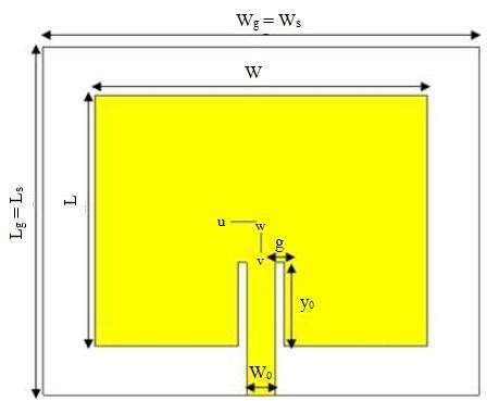
Figure 1 illustrates the geometry of an in set-fed conventional rectangular microstrip patch antenna with full ground plane (FGP). This geometry is designed on FR4 substrate with a dielectric constant (ɛr) of 4.3, and a thickness (h) of 1.6 mm. An inset microstrip feedline is used to excite the patch with a characteristic impedance of 50 Ω. The various parameters of an insetfed microstrip rectangular patch antenna FGP are shown in Table 1
3.3. Phase-II: Rectangular Patch Microstrip Antenna Design with Partial Ground Plane Technique (Proposed Antenna)
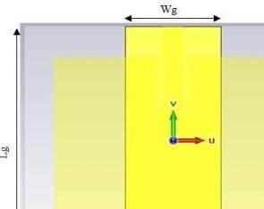
The geometry of an in set-fed microstrip rectangular patch antenna that uses a partial ground plane technique is depicted in Figure 2. In this case, a partial ground plane dimension (Wg × Lg) of 30 mm × 40 mm is used to increase the bandwidth and reduced the return loss of the antenna. Other dimensions of the antenna are the same as the antenna with full ground plane. Table II shows the optimized parameter of the proposed antenna. The parameter is obtained through a series of computer simulation technology (CST) microwave studio optimizations by CST student edition.
Parameters
Value
Partial ground width, Wg 30 mm
Partial ground length, Lg 40 mm
4. RESULTS AND DISCUSSION
The return loss (S11), bandwidth, gain, and directivity of the proposed antenna are analyzed and presented in this section. The simulation has been carried out with the help of computer simulation technology (CST) microwave studio suite 2015 by CST student edition.
4.1. Simulated Results of Antenna with Full Ground Plane (FGP)
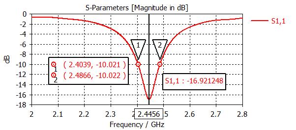
The S11 parameter represents the reflected power from the antenna, which is also known as the reflection coefficient or return loss. If S11= -10 dB, it means that 3 dB of power is supplied to the antenna and -7 dB is reflected. Return loss in telecommunications is a signal reflection caused by irregularities or device insertion in a transmission channel, resulting in impedance mismatch, and is typically expressed in decibels (dB). For the antenna to operate efficiently in practical applications, the return loss for a specific frequency band must be less than or equal to -10 dB. The simulated result for the proposed antenna with full ground is shown in Figure 3. It can be seen that the minimum return loss of the antenna is -16.921248 dB ≈ -16.92 dB at 2.4455 GHz ≈ 2.45 GHz. It has a -10 dB bandwidth of 0.0827 GHz (82.7 MHz).

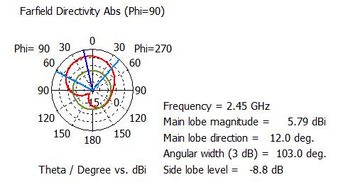
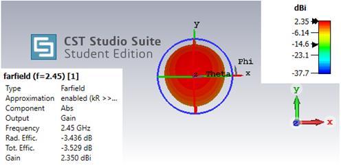
The antenna gain, which is measured in decibels (dB), can be used to demonstrate or study the directional functionality of the antenna. The gain of the antenna is demonstrated in Figure 4. The achieved gain is 2.35 dBi with an efficiency of -3.436 dB. The concentration of radiation pattern of the antenna in a specific direction is measured by directivity. The unit of measurement for directivity is decibels (dB). The higher the directivity, the more concentrated or focused the beam radiated by an antenna. A higher directivity also means that the beam will travel further. The directivity of the antenna is shown in Fig. 5. The directivity pattern shows that, main lobe magnitude is 5.79 dBi, main lobe direction is 12.0 deg, 3dB angular beam width (i.e. HPBW) is 130.0 deg and side lobe level is -8.8 dB.
4.2. Simulated Results of Antenna with Partial Ground Plane (PGP)
The design of an inset-fed microstrip rectangular patch antenna with partial ground plane is shown in Figure 2. The dimension of the partial ground plane is Wg = 30 mm and Lg = 40 mm. The optimum value of return loss (S11) is -27.172909 dB ≈ -27.17 dB at 2.435 GHz and -10dB impedance bandwidth achieved 0.1465 GHz i.e. 146.5 MHz from 2.3618 GHz to 2.5083 GHz, as shown in Figure 6. It has been revealed that changing the ground plane influences the patch
International Journal on AdHoc Networking Systems (IJANS) Vol. 13, No. 1, January 2023
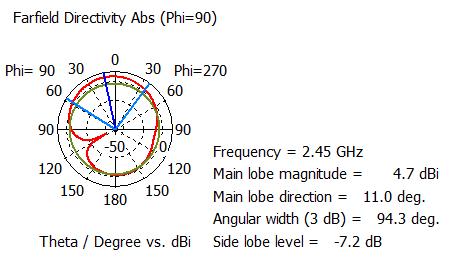
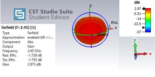
antenna's bandwidth to increase from 82.7 MHz to 146 5 MHz. So this antenna is suitable for a wide range of wireless communication standards, including Bluetooth (2.4 to 2.485 GHz), WiMAX (2.3 to 2.4 GHz), Microwave ovens (2.4 to 2.48 GHz), RFID (2.4 to 2.5 GHz), S-Band (2.3 to 2.4 GHz), Wireless Communication Services (WCS) 2.345 GHz to 2.360 GHz, and 4G LTE (2.3 to 2.315 GHz). The return loss has decreased significantly from -16.92 dB to -27.17 dB, indicating improved impedance matching. The gain of the antenna is demonstrated in Fig. 7. The achieved gain is 2.973 dBi. The far-field directivity of the radiation pattern is shown in Figure 8. The directivity pattern shows that, main lobe magnitude is 4.7 dBi, main lobe direction is 11.0 deg, 3dB angular beam width (i.e. HPBW) is 94.3 deg and side lobe level is -7.2 dB.
Table 3 presents the results of all simulated antennas with full and partial ground planes. Both antenna structures have satisfactory return loss, gain, directivity, and bandwidth values. The proposed antenna has bandwidths of 0.0827 GHz (82.7 MHz) and 0.1465 GHz (146 5 MHz),

International Journal on AdHoc Networking Systems (IJANS) Vol. 13, No. 1, January 2023
respectively. The use of a partial ground plane antenna increased antenna gain while decreasing return loss when compared to a full ground plane antenna. It is also clear that the beam-width of the major lobe has narrowed in the proposed antenna with partial ground plane. The bandwidth of a patch antenna with a partial ground plane is also greater than the bandwidth of a patch antenna with a full ground plane. As a result, antenna performance has improved in patch antennas with partial ground plane, which justifies the theory.
5. CONCLUSION
In this article, a rectangular microstrip patch antenna with partial ground plane (PGP) for ISM band applications has been successfully designed and analyzed to overcome the impediments of a conventional microstrip patch antenna. The simulation has been done by using computer simulation technology (CST) microwave studio suite 2015. After employing a partial ground strategy, the bandwidth (BW) of the proposed has been found to be enhanced The simulation findings show that the suggested antenna attains a BW of 0.1465 GHz i.e. 146 5 MHz, whereas a traditional patch antenna with full ground achieves a bandwidth of 0.0827 GHz i.e. 82 7 MHz In comparison to a conventional patch antenna, the BW increased by 0.0638 GHz i.e. 63.8 MHz from 0.0827 GHz i.e. 82.7 MHz (2.4039 GHz - 2.4866 GHz) to 0.1465 GHz i.e. 146.5 MHz (2.3618 GHz - 2.5083 GHz) Future studies will focus on fabricating the proposed antenna as well as evaluating the performance of the practical and simulated antennas. The existing work would be expanded by integrating the suggested single-component design into an array on a single substrate. This design can offer higher gain, directivity, and efficiency as compared to its single analogue.
REFERENCES
[1] M. H. Tariq, S. Rashid, F. A. Bhatti, “Dual-Band Microstrip Patch Antenna for WiMAX and WLAN Applications”, International Journal of Multidisciplinary and Current Research, vol. 2, pp. 104-108, 2014.
[2] S. C. Gao, L. W. Li, T. S. Yeo, M. S. Leong, “Small Dual-Frequency Microstrip Antennas”, IEEE Transactions on vehicular technology, vol. 51, no.1, pp. 1916-1917, 2002.
[3] Garima, D. Bhatangar, J. S. Saini, V. K. Saxena, L. M. Joshi, “Design of Broadband Circular Microstrip Patch Antenna with Diamond Shaped Slot”, Indian Journal of Space And Physics, vol. 40, pp. 275- 278, 2011.
[4] J. A. Ansari, A. Mishra, N. P. Yadav, P. Singh, “Dual band Slot Loaded Circular Disk Patch Antenna for WLAN Application”, International Journal Of Microwave And Optical Technology, vol.5, no.3, pp. 124-129, 2010.
[5] G. Clementi, N. Fortino, J. Y. Dauvignac, et al., “Frequency and time- domain analysis of different approaches to the backing of an UWB slot antenna”, IEEE Trans. Antennas Propag., vol. 60, No.7, pp.3495
3498, 2012.
International Journal on AdHoc Networking Systems (IJANS) Vol. 13, No. 1, January 2023
[6] N. Ojaroudi, M. Ojaroudi, “Novel design of dual band-notched monopole antenna with bandwidth enhancement for UWB applications”, IEEE Antennas Wirel. Propag. Lett., vol.12, pp. 698– 701, 2013.
[7] G. P. Gao, M. Li, S. F. Niu, X. J. Li, B. N. Li, J. S. Zang, “Study Of Novel Wideband Circular Slot Antenna Having Frequency Band Notched Function”, Progress In Electromagnetic Research(PIER)96, pp.141- 154, 2009.
[8] P. A. Nawle and R. G. Zope, “Rectangular microstrip patch antenna for 2.4 GHz communication using defected ground structure”, IJAFRC, vol. 2, no. 1, pp. 1–11, 2015.
[9] A. R. Chandran, et al., “Microstrip patch-based switched beam antenna at 2.45 GHz for wireless sensor network applications”, Journal of Electromagnetic Waves and Applications, vol. 31, no. 13, pp. 1333
1341, 2017.
[10] Ghaloua, et al., “A Miniature Microstrip Antenna Array using Circular Shaped Dumbbell for ISM Band Applications”, International Journal of Electrical and Computer Engineering (IJECE), vol. 8, no. 5, pp. 3793-3800, 2017.
[11] L. Nageswara Rao, “ Design and Development of Star Shaped Microstrip Patch Antenna for ISM Band Applications”, International Journal of Management, Technology And Engineering, vol. 8, no.11, pp. 1965-1969, 2018.
[12] M. S. Islam, M. I. Ibrahimy, S. M. A. Motakabber, and A. Z. Hossain, “A rectangular inset-fed patch antenna with defected ground structure for ISM band”, In 2018 7th International Conference on Computer and Communication Engineering (ICCCE) (pp. 104-108). IEEE, 2018.
[13] K. S. Ryu, A. Kishk, “UWB antenna with single or dual band-notches for lower WLAN band and upper WLAN band”, IEEE Trans. Antennas Propag., vol. 57, no.12, pp. 3942
3950,2009.
[14] Y. Li, W. Li, W. Yu, et al., “A small multi-function circular slot antenna for reconfigurable UWB communication applications”, IEEE Antennas and Propagation Society Int. Symp. (APSURSI), pp. 834
835, 2014.
[15] A. A. Kalteh, G. R. D. Zadeh, M. N. Moghadasi, et al., “Ultra-wideband circular slot antenna with reconfigurable notch band function”, IET Microw. Antennas Propag., vol.6, no.1, pp. 108–112, 2012.
[16] M. S. Islam, M. T. Islam, M. A. Ullah, G. K. Beng, N. Amin, and N. Misran, “A Modified Meander Line Microstrip Patch Antenna with Enhanced Bandwidth for 2.4 GHz ISM-Band Internet of Things (IoT) Applications,” IEEE Access, vol. 7, pp. 127850–127861, 2019.
[17] M. Karthick, “Design of 2.4GHz patch antennae for WLAN applications,” 2015 IEEE 7th National Conference on Computing, Communication and Information Systems, NCCCIS 2015, pp. 1– 4, Oct. 2015.
[18] A. Arora, A. Rana, A. Yadav, and R. L. Yadava, “Design of microstrip patch antenna at 2.4 GHz for Wi-Fi and Bluetooth applications” , In Journal of Physics: Conference Series, vol. 1921, no. 1, p. 012023, 2021.
[19] A. Tiwari, and D. Sagne, "Parametric Variations of Rectangular Microstrip Patch Antenna Designed for WLAN Application", Helix, vol. 10, no. 4, pp.104-109, 2020.
[20] R. Khatun, M. Rahman, and A. Z. M. T. Islam, "Design of a Compact Rectangular Microstrip Patch Antenna for 2.45 GHz ISM Band", International Journal of Recent Engineering Science, vol. 8, no. 3, 2021.
[21] M. M. Equbal, and S. Ara, "Design of Microstrip Patch Antenna for 2.4GHz Application", International Journal for Research Trends and Innovation, vol. 7, no. 7, 2022.
[22] S. P. Singh, A. Singh, D. Upadhyay, S. Pal, and M. Munde, "Design and fabrication of microstrip patch antenna at 2.4 GHz for WLAN application using HFSS", IOSR Journal of Electronics and Communication Engineering (IOSR-JECE), no. 1(AETM'16), 2016.
[23] C. A. Balanis, Antenna theory: analysis and design, John Wiley & Sons, 2005.