
9 minute read
INSTRUMENT PANEL AND CONTROLS

from K. Tractor Manual
INSTRUMENT PANEL, SWITCHES, AND HAND CONTROLS
(1) Easy Checker™ …69 (2) Tachometer…71 (3) Hazard light switch…45 (4) Turn signal light switch…45 (5) Head light switch…45 (6) Fuel gauge…70 (7) Coolant temperature gauge…70 (8) Hour meter…71 (9) Key switch…45 (10) Tilt lever…45 (11) Hood open lever…46
Advertisement
1. Key switch
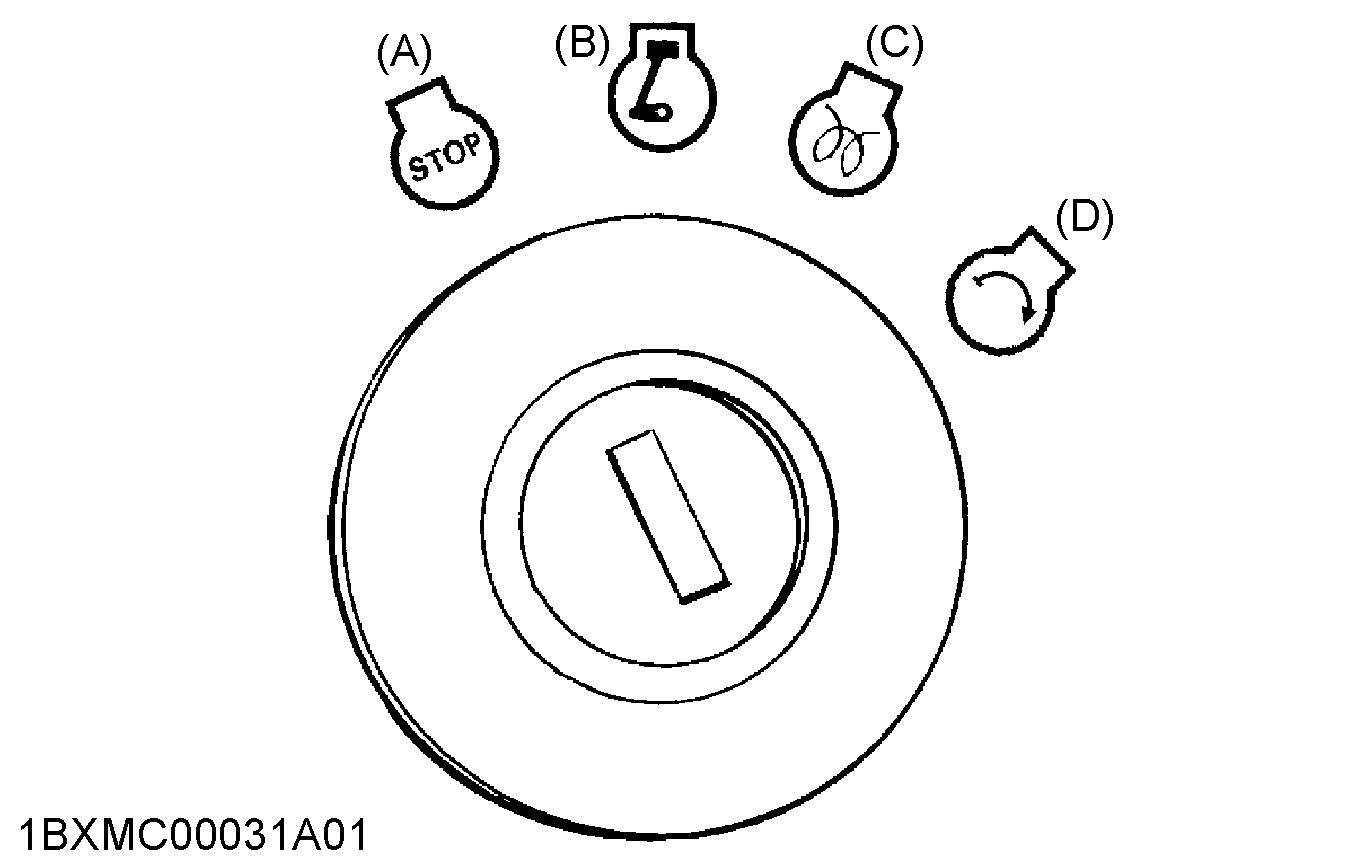
(A) Off (B) On (C) Preheat (D) Start
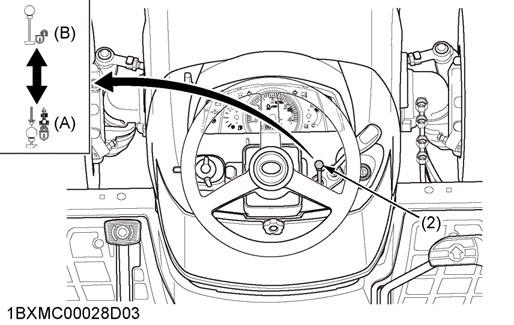
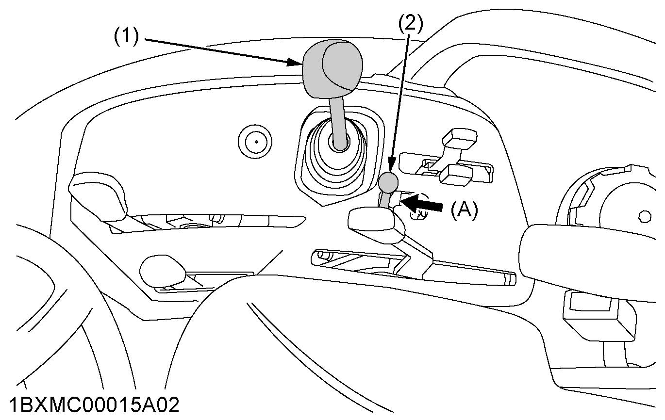
2. Tilt lever
The tilt lever is the lever to adjust the steering wheel to proper position.
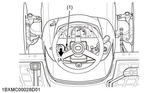
(1) Tilt lever (A) Pull
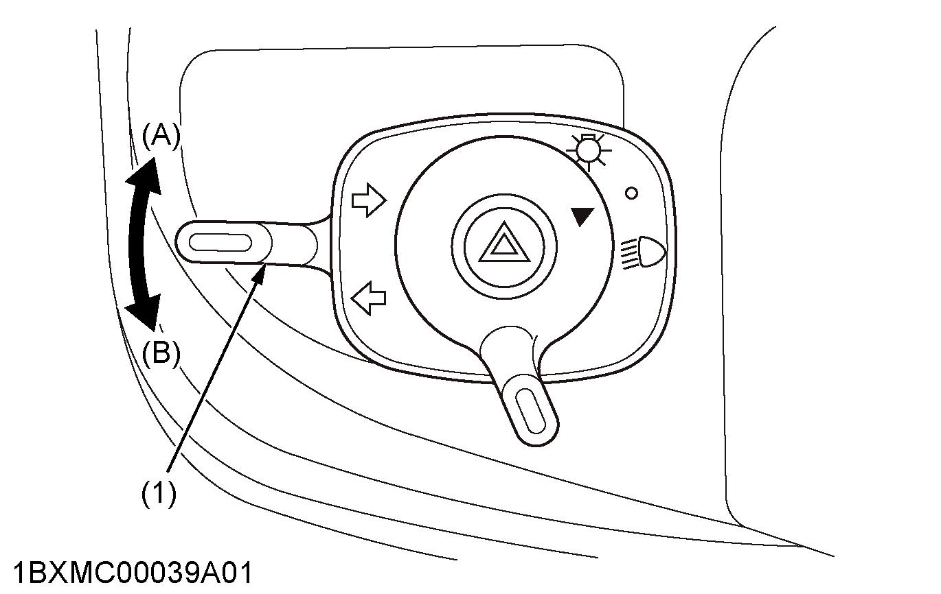
3. Head light switch
To turn on the head lights, turn the head-light-switch clockwise. To turn off the head lights, turn the headlight-switch counterclockwise.
(1) Head light switch (A) On (B) Off
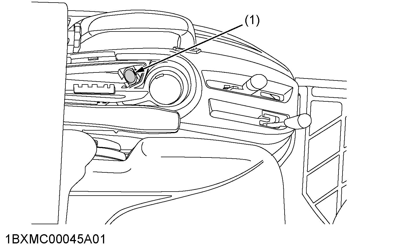
4. Hazard light switch
1. When pressing the hazard-light-switch, the hazard lights flash along with the indicator on the instrument panel. 2. When pressing the hazard-light-switch again, the hazard lights turn off.
NOTE : • The hazard-light-switch is operative when the key switch is only on position.

(1) Hazard light switch (A) Push on-off
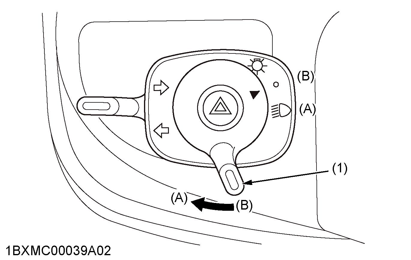
5. Turn signal light switch
To indicate a right turn, turn the turn-signal-light-switch clockwise. To indicate a left turn, turn the turn-signal-light-switch counterclockwise. When the left or right turn signal is activated in combination with the hazard lights, the indicated turning light will flash and the other light will stay on.
NOTE : • Be sure to return the turn-signal-light-switch to center position after turning.
(1) Turn signal light switch (A) Right turn (B) Left turn
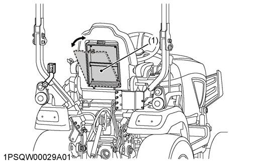
6. Hood open lever
The hood-open-lever is the lever to open the hood.
WARNING
To avoid serious injury or death from contact with moving parts: •Never open the hood or engine side cover while the engine is running. •Do not touch the muffler or the exhaust pipes while they are hot.
Touching the hot muffler or exhaust pipes could cause severe burns.
1.Pull the front guard forward. 2.Pull the hood-open-lever to release the latch to open the hood, and open the hood.
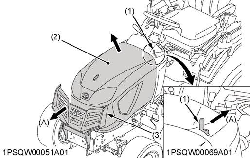
(1) Hood open lever (2) Hood (3) Front guard (A) Pull
FOOT CONTROLS AND HAND CONTROLS
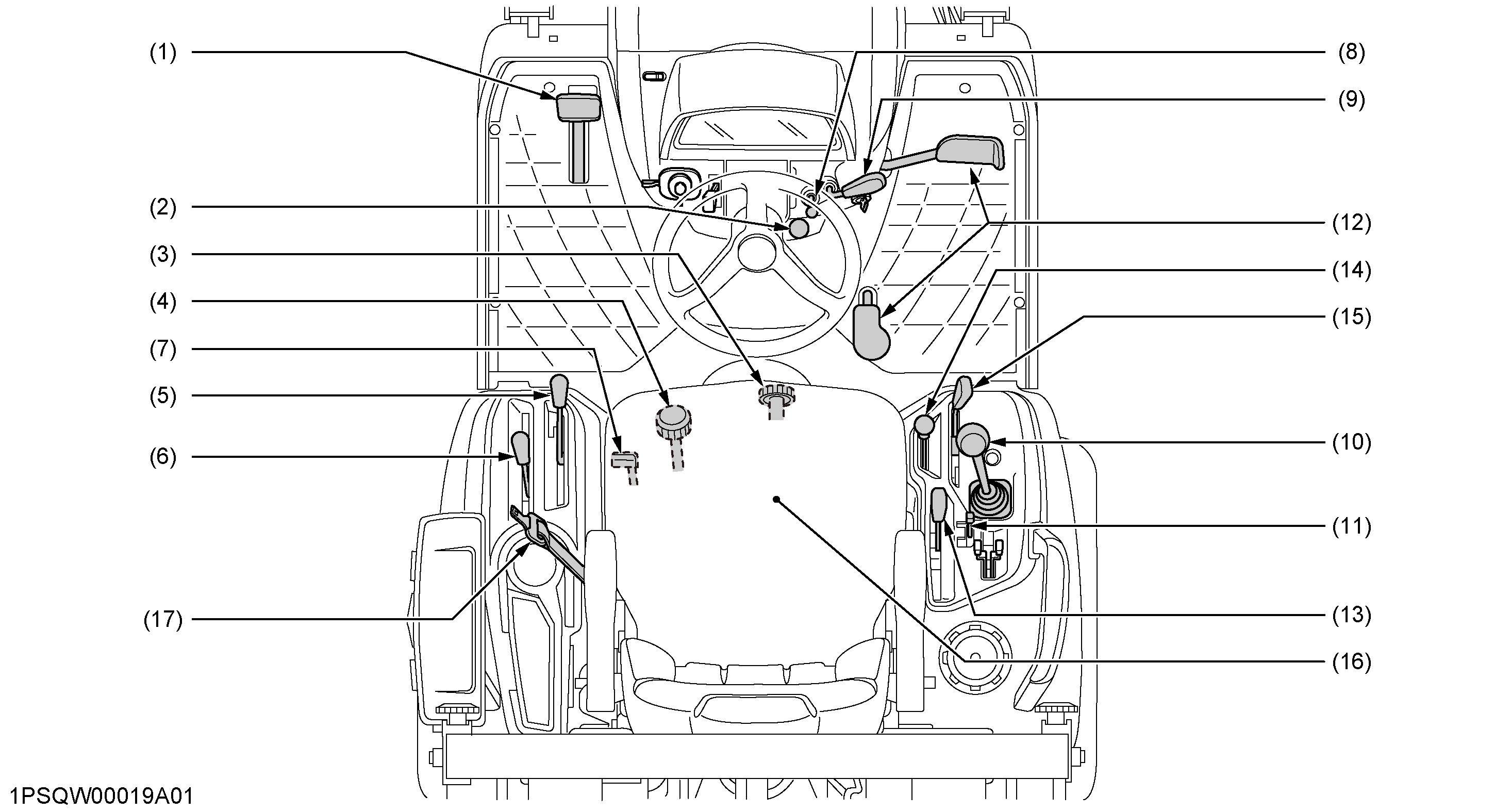
(1) Brake pedal…48, 48 (2) Parking brake lock pedal…48, 48 (3) 3-point hitch lowering speed knob…84 (4) Cutting height control dial…86 (5) PTO clutch lever…77 (6) PTO select lever…77 (7) Differential lock pedal…72 (8) Speed set rod…50, 51 (9) Hand accelerator lever…50 (10) Loader control lever…93, 95 (11) Lock lever…99 (12) Speed control pedal…50 (13) Hydraulic control lever…84 (14) Front wheel drive lever…49 (15) Range gear shift lever (Hi-Lo)…49 (16) Operator's seat…48 (17) Seat belt…48
1. Operator's seat
WARNING
To avoid personal injury or death: •Adjustment to the operator's seat only while the tractor is stopped. •Make sure that the operator's seat is completely secured after each adjustment. •Do not allow any person other than the operator to ride on the tractor.
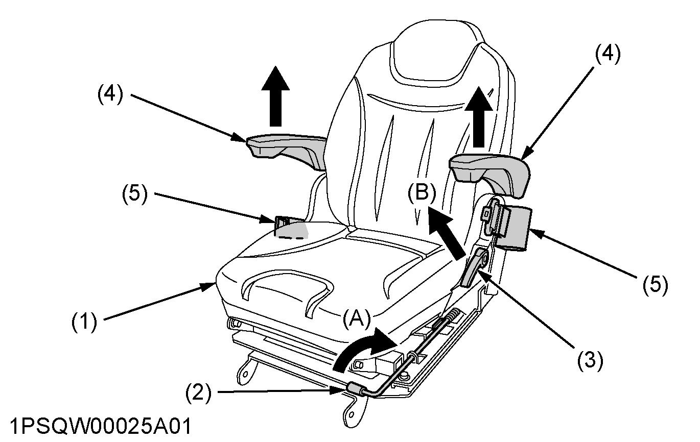
(1) Seat (2) Position adjust lever (3) Backrest tilt adjust lever (4) Arm rest (5) Seat belt (A) Pull up (B) Pull
Travel adjustment
Pull up the position-adjust-lever and slide the seat backward or forward, as required. The seat will lock in position when the position-adjust-lever is released.
Tilt adjustment [BX2380D, BX2680D]
Pull the backrest-tilt-adjust-lever and tilt the backrest to the desired position.
IMPORTANT : •After adjusting the operator's seat, be sure to check that the seat is properly locked. •Be sure the operator's seat is out of contact with the top link. •See REVERSING THE OPERATOR'S SEAT on page 74 when using the operator's seat in the backhoe position.
2. Seat belt
WARNING
To avoid serious injury or death: •Always use the seat belt when the ROPS is installed. •Do not use the seat belt if the tractor is not equipped with ROPS.
Adjust the seat belt for proper fit and connect it to the buckle. The seat belt is auto-locking retractable type.
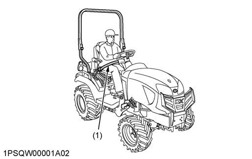
(1) Seat belt
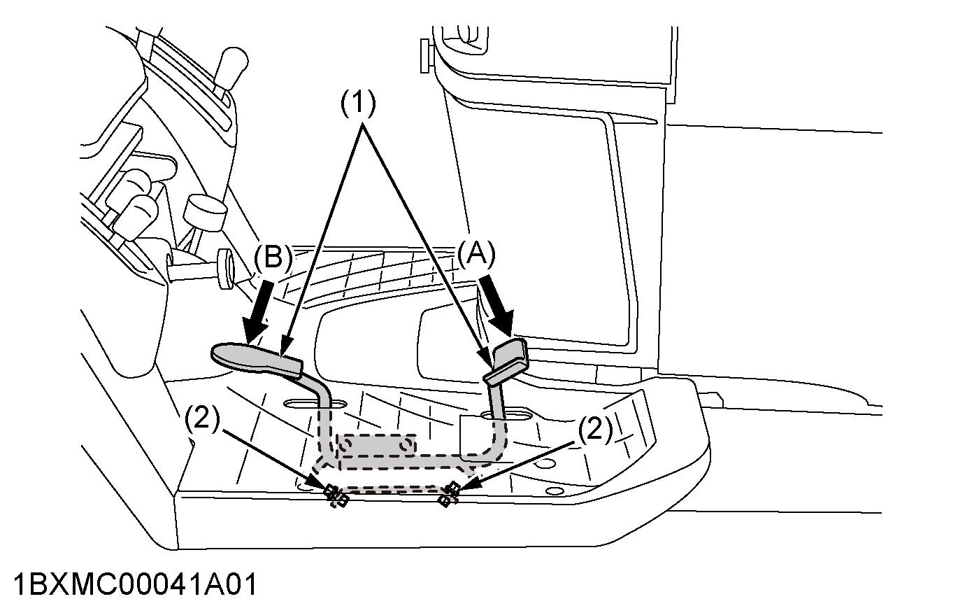
3. Brake pedal and parking brake lock pedal
WARNING
To avoid serious injury or death: •Do not brake suddenly.
An accident may occur as a result of a heavy towed load shifting forward or loss of control. •To avoid skidding and loss of steering control when driving on icy, wet, or loose surfaces, make sure that the tractor is correctly ballasted, operated at reduced speed, and operated with the front-wheel-drive engaged if equipped. •The braking characteristics are different between 2-wheel drive and 4-wheel drive. Know the difference between 2-wheel drive and 4wheel drive and use them carefully. •Engage 4-wheel drive for 4-wheel braking when traveling down a slope.

(1) Brake pedal (2) Parking brake lock pedal (A) Depress (B) Push down parking brake lock pedal while depressing brake pedal
3.1 How to use the parking brake
NOTE : •It is recommended that the operator practice engaging and disengaging the parking brake on
a flat surface without the engine running before operating the tractor for the first time.
To set the parking brake
1.Depress the brake pedal. 2.Latch the brake pedal on pushing and holding the parking-brake-lock-pedal. 3.Release the brake pedal.
(1) Brake pedal (2) Parking brake lock pedal (A) Depress (B) Push down the parking brake lock pedal while depressing the brake pedal
To release the parking brake Depress the brake pedal again.
4. Range gear shift lever (Hi-Lo)
You can shift the range-gear-shift-lever only when tractor is completely stopped.
WARNING
To avoid serious injury or death: •Make sure that the range-gear-shift-lever is fully engaged into the high position or the low position before climbing or descending a slope.
IMPORTANT : Do not force the range-gear-shift-lever. •If it is difficult to shift the range-gear-shift-lever into the neutral “N” position, you should attempt the following procedure. 1.Depress the brake pedal firmly for several seconds. 2.Without reducing the force to depress the brake pedal, shift the range-gear-shift-lever. •If it is difficult to shift the range-gear-shift-lever into the low position or the high position from the neutral “N” position, you should attempt the following procedure. 1.Slightly depress the speed-control-pedal to rotate the gears inside of transmission. 2.Release the speed-control-pedal to the neutral “N” position. 3.Shift the range-gear-shift-lever. •To avoid damage of transmission, stop the tractor before shifting the range-gear-shift-lever between ranges.
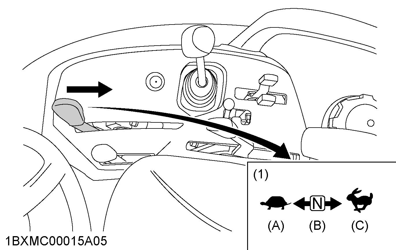
(1) Range gear shift lever (Hi-
Lo) (A) Low (B) Neutral position (C) High
5. Front wheel drive lever
Use the front-wheel-drive-lever to engage the front wheels with the tractor stopped.
WARNING
To avoid serious injury or death: •Do not engage the front-wheel-drive when traveling at road speed. •When driving on icy, wet, or loose surfaces, make sure that the tractor is correctly ballasted to avoid skidding and loss of steering control.
Operate the tractor at reduced speed and engage the front-wheel-drive. •An accident may occur if the tractor is suddenly braked, such as by heavy towed loads shifting forward or loss of control. •The braking characteristics are different between 2-wheel drive and 4-wheel drive. Know the difference and use them carefully.
Shift the front-wheel-drive-lever to the on position to engage the front-wheel-drive.
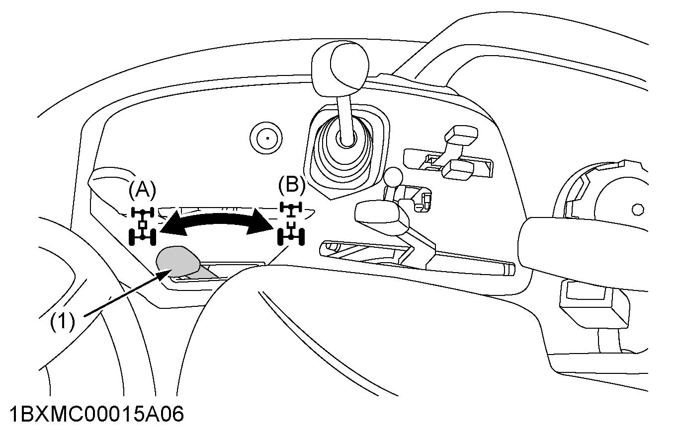
(1) Front wheel drive lever (A) On (B) Off
IMPORTANT : •To avoid damage of transmission, when the front-wheel-drive-lever is not smoothly shifted, slightly depress forward or rearward on the speed-control-pedal. •Tires will wear quickly if the front-wheel-drive is engaged on paved roads.
Front wheel drive is effective for the following jobs:
•When greater pulling force is needed, such as working in a wet field, when pulling a trailer, or when working with a front-end-loader •When working in sandy soil •When working on a hard soil where a rotary tiller might push the tractor forward •Additional braking at reduced speed
6. Hand accelerator lever
Pulling the hand-accelerator-lever back (the position) increases the engine speed, and pushing it forward (the position) decreases engine speed.

(1) Hand accelerator lever (A) Increase (B) Decrease
7. Speed control pedal
WARNING
To avoid serious injury or death: •Do not operate the tractor if it moves on level ground with your foot off the speed-controlpedal.
(1) Speed control pedal (2) Stopper bolts (A) Forward (B) Reverse
IMPORTANT : •To prevent serious damage to the HST, do not adjust the stopper bolts.
Forward pedal
Reverse pedal Depress the forward pedal with the toe of your right foot to move forward.
Depress the reverse pedal with the heel of your right foot to move backward.
NOTE : •When you stand up from the seat with the speed-control-pedal stepped on, the engine will stop regardless of whether the machine is moving or not. Engine stopping is because that the tractor is equipped with the operatorpresence-control-system (OPC).
8. Speed set device
The speed-set-device is designed for tractor-operatingefficiency and operator's comfort. This device will provide a constant forward operating speed by mechanically holding the speed-control-pedal at a selected position.

(1) Speed control pedal (2) Stopper bolts
8.1 How to use the speed set device
To engage the speed set device
1. Accelerate speed to desired level using the speedcontrol-pedal. 2. Push and hold the speed-set-rod downward to on position. 3. Release the speed-control-pedal. 4. Release the speed-set-rod.
Desired speed will be maintained.
To disengage the speed set device
1. Depress the brake pedal.
IMPORTANT : • To prevent the damage of the speed-set-device, do not depress the reverse pedal when the speed-set-device is engaged.
NOTE : • If you step on the speed-control-pedal on the forward acceleration side, the speed-set-device will disengage. • The speed-set-device will not operate in reverse.
(1) Speed control pedal (2) Speed set rod (A) On (B) Off
9. Loader control lever
(1) Loader control lever (A) Down and dump (B) Dump (C) UP and dump (D) Roll back (E) Down and roll back (F) Down (G) Float
ACCESSORY
1. 12 V electric outlet
You may use the 12 V electric outlet to connect an auxiliary light or other devices.
IMPORTANT : • Do not use as a cigarette lighter. • Do not use when wet.
NOTE : • Do not connect a light or other device that draws more than 120 watts to 12 V electric outlet. The battery may discharge very rapidly or the 12 V electric outlet may fail.
(1) 12V electric outlet
2. Glove box
(1) Glove box
