FloVue Final Control System ARROW INDICATES FAIL-OPEN POINT ’A’ O-RING LOCATION
1/8 INCH NPT PORT FOR FIELDVUE CONTROLLER
W6510*A/IL
Figure 5. FIELDVUE Digital Valve Controller Point of Connection (size 20 shown)
4. Figure 5 shows the point of connection for the FIELDVUE digital valve controller. It is mechanically attached by the two socket-head screws removed in step 3. The air output connection is made at point ’A’. Note the location of the O-ring (key 167).
W6511*A/IL
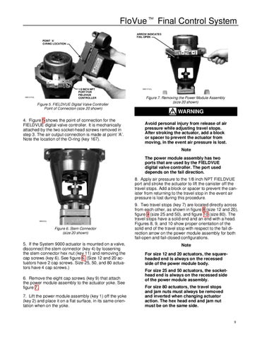
Figure 7. Removing the Power Module Assembly (size 20 shown)
WARNING Avoid personal injury from release of air pressure while adjusting travel stops. After stroking the actuator, add a block or spacer to prevent the actuator from moving, in the event air pressure is lost. Note The power module assembly has two ports that are used by the FIELDVUE digital valve controller. The port used depends on the fail direction. 8. Apply air pressure to the 1/8 inch NPT FIELDVUE port and stroke the actuator to lift the canister off the travel stops. Add a block or spacer to prevent the canister from returning to the travel stop in the event air pressure is lost during this procedure.
W6518/IL
Figure 6. Stem Connector (size 20 shown)
5. If the System 9000 actuator is mounted on a valve, disconnect the stem connector (key 4) by loosening the stem connector hex nut (key 11) and removing the cap screws (key 6). See figure 6. (Size 12 and 20 actuators have 2 cap screws. Size 25, 50, and 80 actuators have 4 cap screws.) 6. Remove the eight cap screws (key 9) that attach the power module assembly to the actuator yoke. See figure 7. 7. Lift the power module assembly (key 1) off the yoke (key 2) and place it on a flat surface, in its same orientation when on the yoke.
9. Two travel stops (key 7) are located directly across from each other, as shown in figure 8 (size 12 and 20), figure 9 (size 25 and 50), and figure 10 (size 80). The travel stops have a solid end and an end with a head. Figures 8, 9, and 10 show proper orientation of the solid end of the travel stop with respect to the fail direction arrow on the power module assembly for both fail-open and fail-closed configurations. Note For size 12 and 20 actuators, the squareheaded end is always on the recessed side of the power module body. For size 25 and 50 actuators, the sockethead end is always on the recessed side of the power module assembly. For size 80 actuators, the travel stops and jam nuts must always be removed and inverted when changing actuator action. The hex head end and jam nut must be on the same side.
9