Quick Start Guide
DVC6200p Digital Valve Controller October 2011
D103562X012
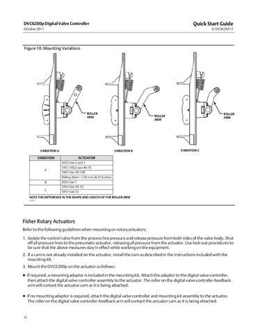
Figure 10. Mounting Variations
ROLLER ARM
VARIATION A
VARIATION B
VARIATION
ROLLER ARM
ROLLER ARM
VARIATION C
ACTUATOR 2052 Size 2 and 3
A
1051/1052 size 40-70 1061 Size 30-100 Sliding‐Stem > 210 mm (8.25 inches)
B
2052 Size 1 1052 Size 20-33
C
1051 Size 33
NOTE THE DIFFERENCE IN THE SHAPE AND LENGTH OF THE ROLLER ARM E1229
Fisher Rotary Actuators Refer to the following guidelines when mounting on rotary actuators: 1. Isolate the control valve from the process line pressure and release pressure from both sides of the valve body. Shut off all pressure lines to the pneumatic actuator, releasing all pressure from the actuator. Use lock‐out procedures to be sure that the above measures stay in effect while working on the equipment. 2. If a cam is not already installed on the actuator, install the cam as described in the instructions included with the mounting kit. 3. Mount the DVC6200p on the actuator as follows: If required, a mounting adaptor is included in the mounting kit. Attach the adaptor to the digital valve controller, then attach the digital valve controller assembly to the actuator. The roller on the digital valve controller feedback arm will contact the actuator cam as it is being attached. If no mounting adaptor is required, attach the digital valve controller and mounting kit assembly to the actuator. The roller on the digital valve controller feedback arm will contact the actuator cam as it is being attached.
12