Instruction Manual
C1 Controllers and Transmitters
September 2009
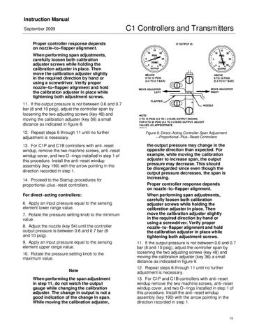
Proper controller response depends on nozzle−to−flapper alignment. When performing span adjustments, carefully loosen both calibration adjuster screws while holding the calibration adjuster in place. Then move the calibration adjuster slightly in the required direction by hand or using a screwdriver. Verify proper nozzle−to−flapper alignment and hold the calibration adjuster in place while tightening both adjustment screws. 11. If the output pressure is not between 0.6 and 0.7 bar (8 and 10 psig), adjust the controller span by loosening the two adjusting screws (key 48) and moving the calibration adjuster (key 36) a small distance as indicated in figure 8.
IF OUTPUT IS:
BELOW 8 TO 10 PSIG (0.6 TO 0.7 BAR)
ABOVE 8 TO 10 PSIG (0.6 TO 0.7 BAR) MOVE ADJUSTER RIGHT
MOVE ADJUSTER LEFT
FLAPPER NOZZLE
NOTE: 3 TO 15 PSIG (0.2 TO 1.0 BAR) OUTPUT SHOWN. FOR 6 TO 30 PSIG (0.4 TO 2.0 BAR) OUTPUT, ADJUST VALUES AS APPROPRIATE. A6154 / IL
12. Repeat steps 6 through 11 until no further adjustment is necessary. 13. For C1P and C1B controllers with anti−reset windup, remove the two machine screws, anti−reset windup cover, and two O−rings installed in step 1 of this procedure. Install the anti−reset windup assembly (key 190) with the arrow pointing in the direction recorded in step 1. 14. Proceed to the Startup procedures for proportional−plus−reset controllers. For direct−acting controllers: 6. Apply an input pressure equal to the sensing element lower range value. 7. Rotate the pressure setting knob to the minimum value. 8. Adjust the nozzle (key 54) until the controller output pressure is between 0.6 and 0.7 bar (8 and 10 psig). 9. Apply an input pressure equal to the sensing element upper range value. 10. Rotate the pressure setting knob to the maximum value. Note When performing the span adjustment in step 11, do not watch the output gauge while changing the calibration adjuster. The change in output is not a good indication of the change in span. While moving the calibration adjuster,
Figure 9. Direct−Acting Controller Span Adjustment —Proportional−Plus−Reset Controllers
the output pressure may change in the opposite direction than expected. For example, while moving the calibration adjuster to increase span, the output pressure may decrease. This should be disregarded since even though the output pressure decreases, the span is increasing. Proper controller response depends on nozzle−to−flapper alignment. When performing span adjustments, carefully loosen both calibration adjuster screws while holding the calibration adjuster in place. Then move the calibration adjuster slightly in the required direction by hand or using a screwdriver. Verify proper nozzle−to−flapper alignment and hold the calibration adjuster in place while tightening both adjustment screws. 11. If the output pressure is not between 0.6 and 0.7 bar (8 and 10 psig), adjust the controller span by loosening the two adjusting screws (key 48) and moving the calibration adjuster (key 36) a small distance as indicated in figure 9. 12. Repeat steps 6 through 11 until no further adjustment is necessary. 13. For C1P and C1B controllers with anti−reset windup remove the two machine screws, anti−reset windup cover, and two O−rings installed in step 1 of this procedure. Install the anti−reset windup assembly (key 190) with the arrow pointing in the direction recorded in step 1.
15