Design BV500 2. Install a three-valve bypass around the control valve assembly if continuous operation will be necessary during inspection and maintenance of the valve.
VALVE BODY
ACTUATOR A
3. A Design BV500 valve is normally shipped as part of a control valve assembly, with a power actuator mounted on the valve. If the valve and actuator have been purchased separately or if the actuator has been removed from the valve, mount and adjust the actuator according to the Actuator Mounting procedure. The necessary measurements cannot be made with the valve installed. 4. Before starting the actual installation of the valve, determine the proper installation orientation of the valve plug (key 5) and actuator. See figure 2.
Note For best shutoff performance it is recommended to install the valve shaft in a horizontal direction. See figure 1. 5. Before installing the valve, make sure the flow direction arrow on the valve matches the actual process fluid flow direction through the valve for the application where the valve will be installed. 6. Install the flange gaskets and insert the valve between the mating pipeline flanges. Use flat sheet gaskets compatible with the process media, or spiral wound gaskets with compression-controlling center rings. 7. For all bodies, install the line bolts and nuts; then, tighten them using accepted bolting procedures. These procedures include, but are not limited to, lubricating the line bolts and hex nuts and tightening the nuts in a crisscross sequence to ensure proper gasket load.
WARNING A Design BV500 valve shaft is not necessarily grounded when installed in a pipeline unless the valve shaft is electrically bonded to the valve. To avoid personal injury or property damage resulting from the effects of a static electricity discharge from valve components in a hazardous atmosphere or where the process fluid is combustible, electrically bond the valve shaft (key 7) to the valve according to the following step.
4
37A6528-A A3143-2/IL
VIEW A-A
A
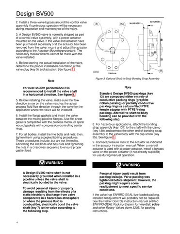
Figure 3. Optional Shaft-to-Body Bonding Strap Assembly
Note Standard Design BV500 packings (key 12) are composed either entirely of conductive packing rings (graphite ribbon packing) or partially conductive packing rings (a carbon-filled PTFE female adaptor with PTFE V-ring packing). Alternative shaft-to-body bonding can be provided with the following step. 8. For hazardous applications, attach the bonding strap assembly (key 131) to the shaft with the clamp (key 130) and connect the other end of bonding strap assembly to the valve body with the cap screw (key 25). See figure 3. 9. Connect pressure lines to the actuator as indicated in the actuator instruction manual. When a manual actuator is used with a power actuator, install a bypass valve on the power actuator (if not already supplied) for use during manual operation.
WARNING Personal injury could result from packing leakage. Valve packing was tightened before shipment; however, the packing might require some readjustment to meet specific service conditions. If the valve has ENVIRO-SEAL live-loaded packing, installed readjustment will probably not be required. See the Fisher Controls instruction manual entitled ENVIRO-SEAL Packing System for Vee-Ball, edisc and other Rotary Valves (form 5305) for packing instructions.