Type 662 4mA SET POINT
4 to 20mA ISOLA TED OUTPUT TO CUSTOMER
R2
R4
R3
R5
Q1
TP1 C1
Jordan Controls Inc. 50B-831587 MC-10796 LOGIC BOARD
R6
20mA SET POINT
R77
R7
R8
R9
R1 1
R13
R15
R10
R12
R14
R16
R17
+16V
U1 R29
C3
C2
R34
2
R36
R30
R33 3 R43
R45
CR12
J1
R37
R19
R20
R21
R22
AR2
R40
U2
C14
1
FEEDBACK POT TERMINALS CR4
R47
C17
+
R74
R61
R52
R38
R39
2
CR1 1
3 R71
R41
C18
CR3
R72 CR6
AR3
HI SET POINT
J2
C8
DEADBAND
C19
3
4
5
6
7
8
R54
R55
R56
R57
LIMIT
1 R58
R60
R42
R61
MOTOR
LO SET POINT A6826/IL
R59
R73 R62
SPEED
DS1 INC CW
C13
+
2
V1
3
V2
4
+16V
5
+5V
6
GND
7
GND
8
SIGNAL
9
U4 MANUAL
10 11
R69
12
+ CURRENT
CR8 2
R67 1
VOL TAGE + R68 4
13 14 15 P2
R63 2
1
CURRENT
MOT ORSPEED
R50
C1 1
C12 CR7 1
C10
1
U3
CR2
J3
2
+ MC1
R53
LO SET POINT
1
CR10
R70
U6
R48
R49
SW1
R27
4 to 20m A ISOLATED OUTPUT
CR5
R46
R25
+
MC2 R44
R26
1
R32
C6
C4
GND
R35
CR9
C6
R24
C7
AR1
R28
C9 R23
+C15
+ C16
R18
20mA
R1
R76
4mA
R75
DEC CCW
R64
DS2
R65
CURRENT
P1
R66
LIMIT
DEADBAND
HI SET POINT
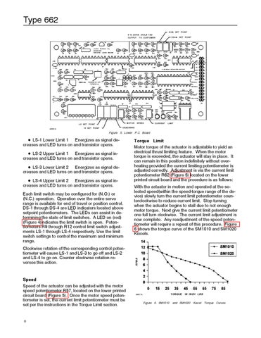
Figure 5. Lower P.C. Board
D LS-2 Upper Limit 1 — Energizes as signal increases and LED turns on and transistor opens. D LS-3 Lower Limit 2 — Energizes as signal decreases and LED turns on and transistor opens. D LS-4 Upper Limit 2 — Energizes as signal increases and LED turns on and transistor opens. Each limit switch may be configured for (N.O.) or (N.C.) operation. Operation over the entire servo range is available for end of travel or position control. DS-1 through DS-4 are LED indicators located above setpoint potentiometers. The LEDs can assist in determining the state of limit switches. A LED on (red) (Figure 4)indicates the limit switch is open. Potentiometers R9 through R12 control limit switch adjustments LS-1 through LS-4 respectively. Use the limit switch settings to control the maximum and minimum range. Clockwise rotation of the corresponding control potentiometer will cause LS-1 and LS-3 to go off and LS-2 and LS-4 to go on. Counter clockwise rotation reverses this action.
Speed Speed of the actuator can be adjusted with the motor speed potentiometer R57, located on the lower printed circuit board (Figure 5). Once the motor speed potentiometer is set, the current limit potentiometer must be set per the instructions in the Torque Limit section.
8
Torque Limit Motor torque of the actuator is adjustable to yield an electrical thrust limiting feature. When the motor torque is exceeded, the actuator will stay in place. It can remain in this position indefinitely without overheating provided the current limiting potentiometer is adjusted correctly. Adjustment is via the current limit potentiometer R62 (Figure 5) located on the lower printed circuit board and the procedure is as follows: With the actuator in motion and operated at the selected speed(within the speed-torque range of the device) slowly turn the current limit potentiometer counterclockwise to reduce current limit. Stop turning when the actuator begins to stall due to not enough motor torque. Next give the current limit potentiometer one full turn clockwise. The current limit adjustment is now complete. Any readjustment of the speed potentiometer will require a repeat of this procedure. Figure 6 shows the torque curve of the SM1010 and SM1020 Kixcels.
RPMS
D LS-1 Lower Limit 1 — Energizes as signal decreases and LED turns on and transistor opens.
TORQUE
A6827/IL
Figure 6. SM1010
IN INCH LBS
and SM1020
Kixcel Torque Curves