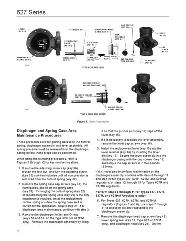
627 Series HAIR PIN CLIP (KEY 13) LEVER (KEY 15)
DIAPHRAGM CASING O-RING (KEY 4)
STEM (KEY 10)
BODY (KEY 1)
DISK ASSEMBLY (KEY 9) STEM BACKUP RINGS (KEY 12)
STEM GUIDE (KEY 8) CAP SCREW (KEY 3)
DIAPHRAGM CASING (KEY 5)
STABILIZER (KEY 7)
STEM O-RING (KEY 11)
BOOST BODY (KEY 6)
PITOT TUBE AND TAB FOR TYPE 627 ONLY
SEAT RING (KEY 2)
W4792
TYPES 627 AND 627R
BLOCKED THROAT BACKUP RINGS (KEY 45)
BLOCKED THROAT (KEY 43)
BLOKED THROAT O-RINGS (KEY 44)
W4791*
TYPES 627M AND 627MR
Figure 5. Stem Assemblies
Diaphragm and Spring Case Area Maintenance Procedures These procedures are for gaining access to the control spring, diaphragm assembly, and lever assembly. All spring pressure must be released from the diaphragm casing before these steps can be performed. While using the following procedures, refer to Figures 7 through 12 for key number locations. 1. Remove the adjusting screw cap (key 36), loosen the lock nut, and turn the adjusting screw (key 35) counterclockwise until all compression is removed from the control spring (key 32). 2. Remove the spring case cap screws (key 37), the nameplates, and lift off the spring case (key 29). If changing the control spring (key 32) or repositioning the spring case (key 29) is the only maintenance required, install the replacement control spring or rotate the spring case so it is correct for the application. Skip to step 21. For diaphragm area maintenance, continue with step 3. 3. Remove the diaphragm limiter and O-ring (keys 50 and 51, on the Type 627H or 627HM only). Remove the diaphragm assembly by tilting 10
it so that the pusher post (key 19) slips off the lever (key 15). 4. If it is necessary to replace the lever assembly, remove the lever cap screws (key 18). 5. Install the replacement lever (key 15) into the lever retainer (key 16) by inserting the lever pin (key 17). Secure the lever assembly into the diaphragm casing with the cap screws (key 18) and torque the cap screws to 7 foot-pounds (9 N•m). If it is necessary to perform maintenance on the diaphragm assembly, continue with steps 6 through 11 and step 20 for Types 627, 627H, 627M, and 627HM regulators, or steps 12 through 19 for Types 627R and 627MR regulators. Perform steps 6 through 11 for Types 627, 627H, 627M, and 627HM Regulators only: 6. For Types 627, 627H, 627M, and 627HM regulators (Figures 5 and 6), use steps 7 through 11 to disassemble and reassemble the diaphragm assembly. 7. Remove the diaphragm head cap screw (key 46), lower spring seat (key 31, Type 627 or 627M only), and diaphragm head (key 24). On the