Model 275 HART Communicator Table 1 DVC5000 Series Digital Valve Controller Factory Default Settings
LOOP
SAFETY GROUND
LOOP +
Setup Parameter Analog Input Units Input High Input Low Travel Range High Travel Range Low Control Mode Restart Control Mode Self-Test Shutdown Dynamic Bypass Input Filter Time Input Characteristic Travel Limit High Travel Limit Low Travel Cutoff High Travel Cutoff Low
HAND HELD TALK −
− AUX +
− LOOP + TEST +
TALK + TEST −
EARTH GROUND
Minimum Opening Time Minimum Closing Time Polling Address
Default Setting mA 20.0 mA 4.0 MA 100 % 0% Remote set Point (RSP) Resume Last All Failures Disabled Disabled 0 secs Linear 125 % –25 % 125 % 0.1 % 0 secs 0 secs 0
TALK + TALK
D Instrument Mode D Control Mode
A6193/G1
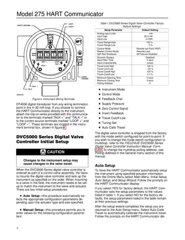
Figure 4. Instrument Wiring Terminals
DT4000 digital transducer from any wiring termination point in the 4–20 mA loop. If you choose to connect the HART Communicator directly to the instrument, attach the clip-on wires provided with the communicator to the terminals marked TALK +’’ and ‘‘TALK –” or to the current source terminals marked ‘‘LOOP +’’ and ‘‘LOOP –’’. These terminals are located in the instrument terminal box, shown in figure 4.
DVC5000 Series Digital Valve Controller Initial Setup CAUTION Changes to the instrument setup may cause changes in the valve travel. When the DVC5000 Series digital valve controller is ordered as part of a control valve assembly, the factory mounts the digital valve controller and sets up the instrument as specified on the order. When mounting to a valve in the field, the instrument needs to be setup to match the instrument to the valve and actuator. There are two initial setup procedures:
D Feedback Char D Supply Pressure D Zero Control Signal D Invert Feedback D Travel Cutoff Low D Tuning Set D Auto Calib Travel The digital valve controller is shipped from the factory with the mode switch configured for point-to-point. If you wish to change the mode switch configuration to multidrop, refer to the FIELDVUE DVC5000 Series Digital Valve Controller Instruction Manual- Form 5335. To change the multidrop polling address, see Polling Address in the General menu section of this manual.
Auto Setup To have the HART Communicator automatically setup the instrument using specified actuator information, from the Online Menu select Main Menu, Initial Setup, Auto Setup, and Setup Wizard. Follow the prompts on the HART Communicator display.
D Auto Setup—this procedure automatically selects the appropriate configuration parameters depending upon the actuator type and size specified.
If you select YES for factory default, the HART Communicator sets the setup parameters to the values listed in table 1. If you select NO for the factory defaults, the setup parameters listed in the table remain at their previous settings.
D Manual Setup—this procedure permits you to enter values for the following configuration parameters:
After the setup wizard completes the setup you are returned to the Auto Setup menu. Select Auto Calib Travel to automatically calibrate the instrument travel. Follow the prompts on the HART Communicator dis-
6