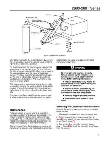
2680-268T Series LEVER B DISPLACER ROD PROPORTIONAL BAND ADJUSTMENT
RELAY
PIVOT POINT O
ZERO SPRING LEVER A
DISPLACER
A5592 / IL
Figure 6. Operational Schematic
relay compensates for the force imbalance by converting it to a pressure output to a control valve and bringing the forces back into equilibrium. For throttling control, the relay pressure output will be proportional to the buoyant force. For on-off control, the relay pressure output will be either zero or equal to the supply pressure over the range of liquid level change. The liquid level change required to fully operate the relay is adjusted by sliding the proportional band adjustment along lever A to vary the lever ratio between levers A and B. With reverse-acting proportional control, the principle of operation remains the same as that for direct action; however, the controller delivers an increasing pneumatic signal to the control valve when the liquid level falls. Operation of the Type 2680E is similar, except rising or falling levels opens or closes the electrical switch.
al tolerances, etc.), use only replacement parts manufactured by Fisher.
WARNING To avoid personal injury or property damage caused by the release of pressure or process fluid, observe the following before starting maintenance: Provide some temporary means of control for the process before taking the controller out of service. Provide a means of containing the process fluid before removing any measurement devices from the process. Vent any trapped process pressure. Shut off electrical power to Type 2680E.
Removing the Controller From the Sensor
Maintenance Parts are subject to normal wear and must be inspected periodically and replaced as necessary. The frequency of parts inspection and replacement depends upon the severity of service conditions. When inspection or repairs are required, disassemble only those parts necessary to accomplish the task. Due to the care Fisher Controls takes in meeting all manufacturing requirements (heat treating, dimension-
Observe the warning given at the start of the Maintenance section. 1. Disconnect the supply and output pressure lines. 2. Slide the hook end of the zero spring (key 5, figure 8) over and off the controller end of the displacer rod (key 3, figure 7). 3. Remove the four controller mounting screws (key 11, figure 8), and pull the controller straight away from the sensor.
9