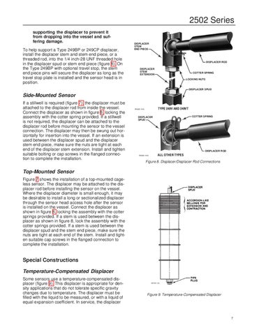
2502 Series supporting the displacer to prevent it from dropping into the vessel and suffering damage. To help support a Type 249BP or 249CP displacer, install the displacer stem and stem end piece, or a threaded rod, into the 1/4 inch-28 UNF threaded hole in the displacer spud or stem end piece (figure 8). On the Type 249BP with optional travel stop, the stem end piece pins will secure the displacer as long as the travel stop plate is installed and the sensor head is in position.
DISPLACER STEM END PIECE
DISPLACER ROD DISPLACER STEM EXTENSION
COTTER SPRING LOCKING NUTS
DISPLACER SPUD
Side-Mounted Sensor If a stillwell is required (figure 7), the displacer must be attached to the displacer rod from inside the vessel. Connect the displacer as shown in figure 8, locking the assembly with the cotter spring provided. If a stillwell is not required, the displacer can be attached to the displacer rod before mounting the sensor to the vessel connection. The displacer may then be swung out horizontally for insertion into the vessel. If an extension is used between the displacer spud and the displacer stem end piece, make sure the nuts are tight at each end of the displacer stem extension. Install and tighten suitable bolting or cap screws in the flanged connection to complete the installation.
W0229-1A/IL
COTTER SPRING
DISPLACER SPUD
DISPLACER ROD W0228-1A/IL
Figure 8. Displacer/Displacer Rod Connections
Top-Mounted Sensor Figure 7 shows the installation of a top-mounted cageless sensor. The displacer may be attached to the displacer rod before installing the sensor on the vessel. Where the displacer diameter is small enough, it may be desirable to install a long or sectionalized displacer through the sensor head access hole after the sensor is installed on the vessel. Connect the displacer as shown in figure 8, locking the assembly with the cotter springs provided. If a stem is used between the displacer as shown in figure 8, lock the assembly with the cotter springs provided. If a stem is used between the displacer spud and the stem end piece, make sure the nuts are tight at each end of the stem. Install and tighten suitable cap screws in the flanged connection to complete the installation.
Special Constructions Temperature-Compensated Displacer Some sensors use a temperature-compensated displacer (figure 9). This displacer is appropriate for density applications that do not tolerate specific gravity changes due to temperature. The displacer must be filled with the liquid to be measured, or with a liquid of equal expansion coefficient. In service, the displacer
A0746–1/IL
Figure 9. Temperature-Compensated Displacer
7