Type 1808 & 1808A
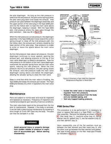
the pilot diaphragm. As long as the inlet pressure is lower than the set pressure, the pilot control spring pushes the pilot valve plug down and closes the exhaust. Inlet pressure can pass between the diaphragm assembly and the upper portion of the valve plug in the Type 6358 pilot and into the hollow stem to load the main valve above the diaphragm, keeping it closed. With the Type 6356 pilot, inlet pressure enters the main valve through the pilot restriction. (See key 20 in figure 5.) When the inlet pressure is at set pressure, the diaphragm assembly in the Type 6358 pilot moves toward the control spring enough to close off the inlet pressure path into the hollow stem; the exhaust port remains closed by the lower portion of the valve plug. Now pressure is unable to enter or leave the space above the main valve diaphragm. As the inlet pressure rises above set pressure, the pilot diaphragm continues to move upward, opening the exhaust port, and allowing pressure on the top of the main valve diaphragm to bleed to atmosphere. Now the inlet pressure on the bottom of the main valve diaphragm overcomes the actuator spring force and the main valve opens, reducing the inlet pressure. When the inlet pressure returns to set pressure, the pilot spring closes the exhaust, and inlet pressure loads the main valve diaphragm casing above and below the diaphragm, allowing the actuator spring to close the main valve. Keep in mind that while the main valve is throttling, the Type 6358 pilot keeps the exhaust port closed. The Type 6358 pilot bleeds only when it repositions the main valve plug.
Maintenance Parts are subject to normal wear and must be inspected and replaced as necessary. Frequency of inspection and maintenance depend upon severity of service conditions. The main valve body need not be removed from the line prior to maintenance. However, if the body is removed, it can be held in place during maintenance by screwing a short length of 2-inch NPT pipe into the body. The pipe can then be clamped in a vise.
UPPER PORTION OF VALVE PLUG TO EXHAUST PORT LOWER PORTION OF VALVE PLUG TO MAIN VALVE DIAPHRAGM
DIAPHRAGM ASSEMBLY HOLLOW PASSAGE IN VALVE PLUG STEM INLET PRESSURE LOADING PRESSURE EXHAUST
PILOT EXHAUST PILOT CONTROL SPRING PILOT CONTROL LINE
ACTUATOR SPRING
VALVE PLUG
MAIN VALVE EXHAUST
MAIN VALVE INLET 32A0847-A 32A0846-A 36A2951-B A2542-1
Figure 3. Schematic of Type 1808 Pilot-Operated Backpressure Regulator or Relief Valve
• Isolate the relief valve or backpressure regulator from line pressure, • Release trapped pressure from the body and any isolated piping, and • Vent any trapped loading pressure.
P590 Series Filter This procedure is to be performed if it is necessary to clean or replace filter parts in a Type P593-1 or P594-1 filter assembly. Remove the following as shown in figure 4: filter body (key 1), machine screw (key 4), spring washer (key 6), gasket (key 7), two flat washers (key 5), and filter element (key 2).
WARNING Avoid personal injury or property damage from sudden release of pressure or explosion of accumulated gas. Before starting disassembly:
4
Upon reassembly, one of the flat washers must go between the filter element and filter head (key 3), and the other must go between the filter element and gasket. Use pipe thread sealant on the filter head pipe threads as indicated in figure 4.