14 minute read
Assembly Instructions

from Eddy manual
by returos

NOTICE: The following steps are only a general guide to assist the assembling process of your E-bike and is not a complete or comprehensive manual of all aspects of assembly, maintenance, and repair. We recommend you to consult a certified bike mechanic to assist in the assembly, repair, and maintenance of your E-bike.
Step 1
Advertisement
Unpack the bike. Open the bike box and remove the small box inside. With the help of someone who is capable of safely lifting a heavy object, remove the Ebike from the bike box. Carefully remove the packaging materials protecting the bike frame and all other components. Please recycle packaging materials, especially the cardboard and the foam. Open the small box and carefully set out all contents. The following should be included with the EDDY JOBOBIKE:
Front Wheel Manual Assembly Toolkit Front Fender and Rear Fender (installed) Front wheel axle
If there are any missing parts, please contact Jobobike. Charger Keys ( 2 identical) Headlight Pedals
11
Step 2
Install handlebar onto stem as shown in the assembly video for the EDDY JOBOBKE located on the web page JOBOBIKE.pl/instructions 2. 1. Rotate the handlebar stem upward so that it is upright with the hinge closed. Be cautious to keep fingers, clothes, and everything else away from the hinge. 2. 2. Secure the stem clasp to release lever. Fold the stem clasp release lever up and press it towards the stem until the release lever clicks into place. 2. 3.Get help from a bike-fitting professional. Consult a certified bike-fitting specialist for assistance to fit the bike properly for safety, optimal fit, and bike ergonomics. Step 3
Install the front wheel as shown in the EDDY Assembly Video available on the web page JOBOBIKE.pl/instructions/. 3. 1. Put the E-bike in a safety, stable position – under the hard foam that came in carton box under the fork. 3. 2. Prepare the wheels – if there are any wheel hub protection, please remove. 3. 3.Unscrew the nut from one side of the axle and put it inside the wheel hub in the correct position. It is important to leave some space for the washer on the side where brake disk is located. 3. 4. Carefully put the wheel inside the fork nests and tighten the nuts. When properly installed, the front wheel should be at the center of the front fork, the brake rotor should be between the brake pads in the brake caliper. Make sure that the front wheel is properly secured before moving on to the next step.

12
Never touch the brake rotor, especially when the wheel and/or bike is in motion, or serious injury could occur. Hand oils can cause squeaking and decrease brake performance; do not touch the brake rotorwhile inspecting, opening, or closing the quick release lever.
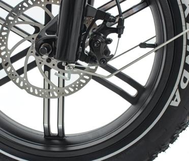
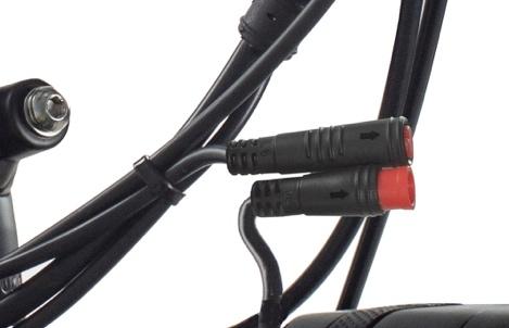
Step 4 Install the pedals. Locate the pedal that has a smooth pedal axle exterior and a“R” stamp at the right end. The right pedal goes onto the crank on the right side of the bike (which has the drivetrain gears and locates at the rider’s right side when riding). The right pedal is threaded to tighten by turning clockwise (towards the bike’s front) . Carefully thread the right pedal onto the crank on the right side of the bike by hand. Do not cross thread or damage the threads. The left pedal is reverse-threaded and tightens counterclockwise (towards the bike’s back). Ensure that the remaining pedal has notches on the exterior of the axle and a “L” stamp at the left end of the axle , indicating it is the left pedal. Carefully thread the pedal onto the left crank slowly by hand. Do not cross thread or damage the threads. Torque each pedal to 35 Nm. Use a pedal wrench to avoid damage caused by wider wrenches. Step 5 Install the front fender and the headlight as shown in the assembly video available on the web page JOBOBIKE.pl/instructions/ 5.1. Remove the fender and headlight mounting bolt from the fork arch and set them aside. 5.2. Place the fender in position. Pass the fender through the front fender mounting point under the front fork arch from the back of the front tyre. 5.3 Plug in the headlight. Locate the two sides of the red, two-pin headlight connector, carefully align the internal pins and notches with external arrows, then press them directly together without


13
twisting to fully seat the connection. 5.4. Attach the headlight and fender to the fork arch. Pass the headlight mounting bolt through a washer, the headlight mount, the fender mounting point, the fork arch mounting point, a second washer, and then thread the locknut onto the bolt end. Use a 5 mm hex wrench at the bolt head and a 10 mm wrench on the locknut at the end of the bolt and tighten evenly. Attach the fender mounting arms to the front fork. Ensure that the fender is centred and torque al l mounting bolts to the recommended torque value (6 Nm). Ensure the fender clamps on both sides are parallel.
5.5. Adjust the headlight angle to illuminate the road ahead but not to blind oncoming traffic. Use a 3 mm hex wrench and 8 mm wrench to loosen the headlight angle adjustment bolt, tilt the headlight to the optimal position, and then tighten in place securely.

14
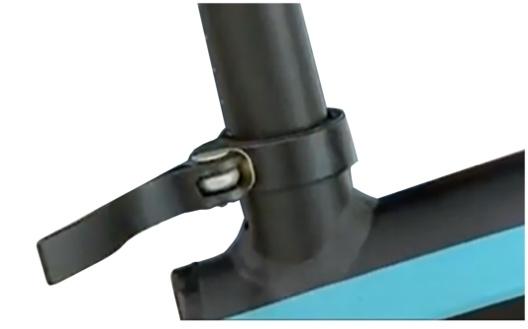
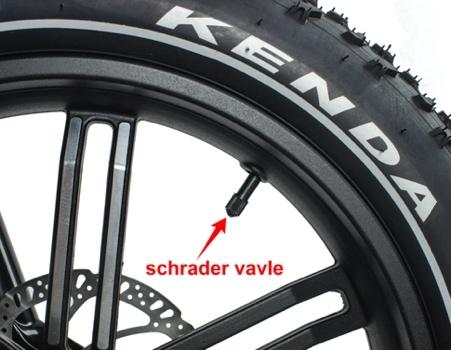
Step 6 Inflate the tyres. Check that the tyre beads and tyres are evenly seated on the rims. Use a pump with a Schrader valve and pressure gauge to inflate each tyre to the recommended pressure value indicated on the tyre sidewall, 20-30 psi (1.4 – 2.1 bar). Do not overinflate or underinflate tyres. Step 7 Set the desired seat height. Open the quick release lever by hinging it open fully. Ensure that the seat post clamp opening is aligned with the notch at the front of the seat tube. Adjust the seat post up or down to a comfortable height, while ensuring that the seat post is inserted into the frame past the minimum insertion point.If needed, use the thumb nut to add tension to the clamp so there is enough resistance when the lever is in line with the clamp bolt, but do not overtighten. Close the quick release lever to secure the seat post and make sure that it does not move. See the Adjusting the Seat section of this manual for more details.

15
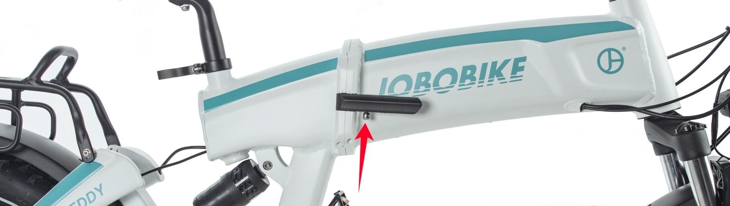
Step 8 Secure the folding mechanisms. Check to make sure that the central frame hinge is latched and securely locked, as shown in the assembly video available on the web page: JOBOBIKE.pl/instructions/. Be cautious to keep fingers, clothing, and everything else away from the folding parts and potential pinch points. Always remember to make sure that the frame folding mechanism latch and handlebar folding mechanism latch are both locked before moving or riding the bike.
Step 9 Always check that the battery is locked to the frame of the E-bike before riding. Operate the electrical system when the battery has been adequately charged and the battery is secured to the mounting receptacle on the frame.
16
Step 10 Ensure all hardware is tightened properly following recommended torque values. Recommended Torque Values
Hardware Location Handlebar Area Handlebar Area Handlebar Area Handlebar Area Brakes Brakes Brakes Brakes Seat post area Rear Dropout Area Rear Dropout Area Rear Dropout Area Rear Dropout Area Rear Dropout Area Rear Dropout Area Rear Dropout Area Bottom Bracket and Crank Area Bottom Bracket and Crank Area Bottom Bracket and Crank Area Bottom Bracket and Crank Area Bottom Bracket and Crank Area Fenders Hardware Handlebar Stem Clamp Bolts Handlebar Stem Faceplate Bolts Brake Lever Clamp Bolt Shifter Clamp Screw Calliper Adapter to Frame Calliper to Adapter Brake Cable to Calliper Clamp Brake Rotor to Hub Seat Angle Adjustment Bolt Rear Axle Nuts Rear Torque Arm Bolt Derailleur Bash Guard Mounting Bolts Derailleur Hanger Mounting Bolt Derailleur Mounting Bolt Derailleur Cable Pinch Bolt Kickstand Mounting Bolts Bottom Bracket and Lockring Crank Arm Bolt into BB spindle Pedal into Crank Arm Chainring Bolts Controller Mounting Bolts All Fender Mounting Bolts and Hardware Torque Required (Nm) 15 6-8 6 3 6-8 6-8 6-8 7 18 45 5 5 6 10 6-8 8 45 35 35 10 6 6
17
Step 11 Review the remainder of the manual.
Once the bike has been assembled following the instructions above, read, understand, and follow the procedures outlined in the remainder of the manual before operating the bike. NOTICE: If you have any questions regarding the assembly of your bike, contact JOBO Bikes. If you are unsure if all the assembly steps in the assembly video are performed properly, or you are unable to view the assembly video, please consult a certified local bike mechanic for assistance in addition to contacting JOBO Bikes for help. NOTICE: Ensure that all hardware is tightened properly following recommended torque values. Also ensure that all safety checks in the following sections are performed before the first use of the bike.
Do not extend any components including the handlebar stem, seat post, or seat saddle beyond any minimum insertion marking etched into the components. Ensure that all hardware is properly tightened (to the values in the Recommended Torque Values table) and components are secured before moving on to the next step, otherwise, bike damage, serious injury, or even death could occur.
Rider’s Comfort Generally, for the most comfortable riding position and the best pedaling efficiency, the seat height should be set correctly in relation to the rider’s leg length, as described in the Adjusting the Seat Height section, allowing the knees to be slightly bent with the ball of the foot still on the pedal when the pedal is at the lowest point at the bottom of each stroke. Depending on a rider’s preference, ability, and amount of experience with bikes and E-bikes, lowering the seat so the rider can put one or both feet on the ground without dismounting from the seat. This may offer a safer and more comfortable experience while operating the bike.
18
To obtain the maximum comfort, riders should not overextend their arms’ reach when riding. It is generally advised to ensure that the handlebar and brake lever angles allow a comfortable arm position and relatively straight line from forearms, wrists, and hands. Ensure that the handlebar angle is adjusted so that the handlebar does not contact the rider’s body while turning. A bike fitting professional, such as a certified bike mechanic who specializes in bike fitting, should be consulted to ensure you have a good fit.

NOTICE: If you have any questions regarding the proper fit of your bike, please consult a certified local bike mechanic for assistance or contact JOBOBIKE.
Adjusting the Seat Height For most users, the seat height should be set by placing the ball of their foot on the pedal when the pedal is at its lowest point. In this orientation, their legs should be almost fully extended, with a slight bend at the knee. The correct seat height should not allow leg strain from overextension and the hips should not rock from side to side when pedaling. To adjust the seat height: 1.Open the quick release lever by swinging the lever open and outwards fully . 2. Move the seat up and down by sliding the seatpost in or out of the seat tube. Set the desired seat height.

NOTICE: Ensure that both the seatpost and seat are both properly adjusted before riding. DO NOT raise the seatpost beyond the minimum insertion marking etched onto the seatpost tube
19
(as shown at figure). If the seatpost projects from the frame beyond these markings (shown far right), the seatpost and the frame may break, which could cause a rider to lose control and fall. Ensure that the minimum insertion markings on the seatpost are inside the seat tube of the frame (as pictured on the right).
3. After tightening the adjustment nut (opposite the quick release lever) on the seatpost quick release properly, close the quick release lever fully so it looks like the image below and the seat cannot move up, down, to the left, or right.
Before using the bike, always check to ensure all latches, levers, and quick releases are properly secured and undamaged. Check that they are correctly secured before every ride and after every time the bike is left unsupervised, even for a short time. Otherwise, the handlebar stem and/or seatpost may come loose and can result in loss of control, damage to the bike/property, serious injury, or death.
Adjusting the Seat Position and Angle
To change the angle and horizontal position of the seat: 1. Use a 6 mm hex wrench to loosen the seat adjustment bolt (pictured at right) underneath the seat on the clamp positioned right underneath the seat, above the rear wheel.

2. Once the bolt and clamp are adequately loose, rotate the front of the seat up or down to adjust the angle of the seat; a seat position horizontal to flat ground is desirable for most riders. Move the seat backwards or forwards within the white limit markings on the seat rail, which show the minimum and maximum horizontal movement allowed for this component. Do not exceed these limits.
20
3. While holding the seat in the desired position, use a 6 mm hex wrench to tighten the seat adjustment bolt securely.
NOTICE: Prior to first use, be sure to tighten the seat clamp via the seat adjustment bolt properly. A loose seat clamp or seatpost adjustment bolt can cause bike/property damage, loss of control, a fall, serious injury or death. Periodically check to make sure that the seat clamp is properly tightened.
Adjusting the Suspension Fork
The suspension fork can move up and down up to 80 mm to cushion bumps in the riding surface, which can make riding on a rough road or trail smoother and more comfortable. Depending on a rider’s preference, the suspension fork can be locked out as a rigid fork, which will typically yield higher pedaling efficiency.
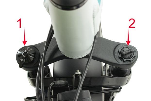
The lockout lever (1) located on top of the right side of the suspension fork, can be turned counterclockwise until it stops to completely lock out the suspension fork’s motion. To unlock the lockout lever, turn the knob clockwise until it stops. When the lockout lever is unlocked, resistance can be adjusted by turning the pre-load adjustment knob (2) which is located on the top of the left side of the suspension fork. To soften the ride, reduce resistance by turning the pre-load adjustment knob counterclockwise, in the direction of the small “-” on the knob. To make the suspension stiffer when going over bumps, add resistance by turning the pre-load adjustment knob clockwise, in the direction of the small “+” on the knob.
21
Folding and Unfolding the Frame

1. Stand at the left side of the bike and make sure that the cranks are parallel to the ground. 2. Release the central frame hinge; pull the folding mechanism lock (the small silver ball at the bottom) towards the front and then pull the black arm back towards the bike. Support bike frame on your leg. 3. Continue to fold the bike until the two sides of the frame are next to each other, turning the front wheel slightly to the left to facilitate folding if needed. Rest the bike on the frame stand under the cranks. Secure the frame with the Velcro strap if desired. 4. Reverse the steps to unfold the frame and securely lock the central frame hinge. 5. NOTICE: Be cautious to keep fingers, clothing and everything else away from the folding parts and any potential pinch points. Always remember to make sure that both the frame folding mechanism latch and handlebar folding mechanism latch are locked before moving or riding the bike. Before each ride, visually inspect the frame for proper alignment and ensure that all hardware is properly secured. Folding Handlebar Stem Features 1. Release (red button/lever) 2. Hex Bolt Set Screw (2.5 mm) 3. Hex Bolt (7 mm) 4. Rolling Pin 5. Rolling Pin Set Screw (2 mm) Folding Handlebar Stem Operation Securing the Handlebar Stem in the Unfolded (Ready to Ride) Position:
22