6 minute read
BA3 Technologies Part A: Building Case Study (BCS) Detailed Envelope Study


Atelier CPU Regina Jedrzejek
Case Study 3
Advertisement
Olympic House in Lausanne
Year of completion: 2019
Architects: 3XN, IttenBrechbühl
Structural engineers: Ingeni
Facade offices: Frener & Reifer
1. THEORY & STRATEGY
NET ZERO EMBODIED CARBON EMISSIONS
• For a new construction 75% of former building’ material was recycled, resulting in some non-structural elements being made 100% from recycled aggregate and up to 30% of structural elements including recycled concrete.
• All of the demolition waste from pre-existing structure was recycled and used for waterproof wall and basement walls, resulting in reduced embodied carbon, savings in natural resources and minimised waste diverted to landfill.
• All of the wooden materials (including furniture) were verified by Forest Stewardship Council to make sure their ethical, responsible sourcing.
• Flexible, open layout enables easy adaptation and potential, future reuse. The carbon footprint of structure was thoroughly analysed to ensure meeting LEED, SNBS and Minergie P certification.
SUSTAINABLE LIFECYCLE COST
• To ensure efficient management IOC collaborated with IMMA, which provided ‘lean management’ - a systematic steering and planning method that targets to waste reduction and fasten project development.
• The costs, safety and efficiency of the structure were firstly estimated, later controlled and improved during construction and have been monitored ever since to ensure efficient performance.
• Health and well-being of current and future users were considered and provided through prioritising daylight, flexible working spaces, active transport routes and connection with green exterior.
Since the beginning stages architects were striving for self-sufficient, highly sustainable structure; using passive energy strategies (thermal mass, solar panels) and renewables on site (lake-water heat pumps, rainwater collection system) ensures efficient, long-therm performance.
ENVELOPE - ENVIRONMENTAL IMPACT
The essential feature of envelope design that contributes to its high thermal and acoustic performance is double-skin facade. The decision to double the amount of triple glazing through suspended structure contributed to improved acoustics, access to natural light (with reduced glare and heat gains thanks to the suspended facade which acts like a sunscreen).Adding vertical, silicone caulk joints and aluminium frame contributed to its moisture resistance.
Another interesting design aspect is the roof choice material - combination of timber and steel frame on reinforced concrete slab was probably dictated by the lightweight properties of timber frame. In the terms of ecology and reuse, the 75% of previous building’s material was recycled and used in structural and non-structural materials, which reduced embodied carbon and amount of demolition waste.
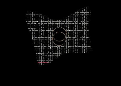
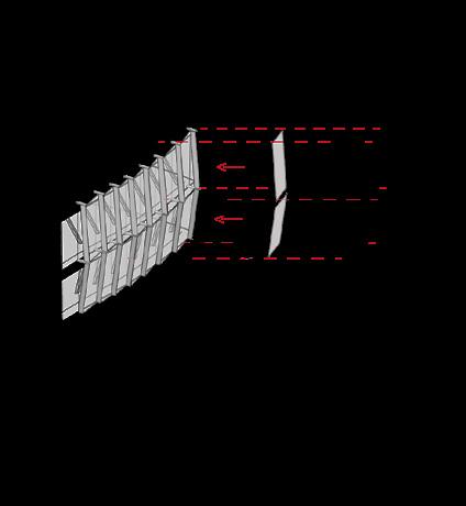
2. INTEGRATED 3D ENVELOPE STUDY
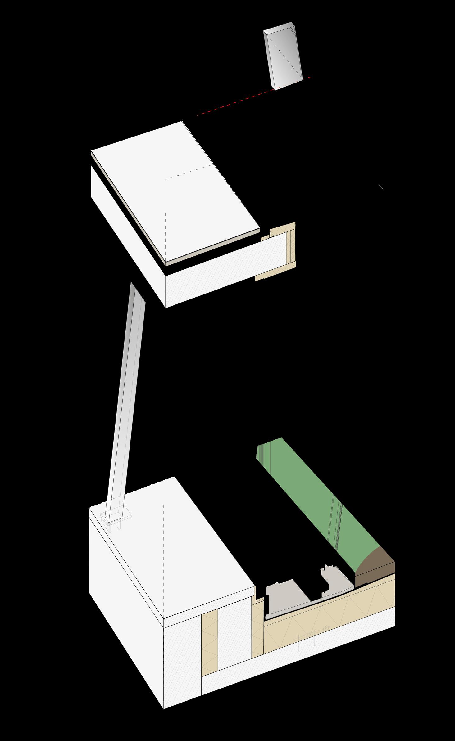
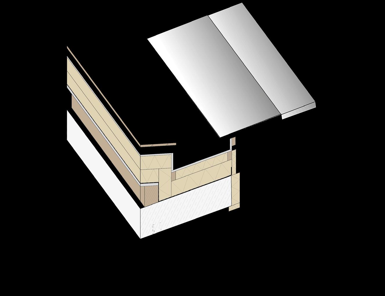
2.1 ISOMETRIC BAY
SCALE 1:50
30 mm sheet aluminium panels 100/120 mm metal L-profile (for drainage) 30 mm metal grating on steel profile frame 180 mm steel beams
Vapour barrier
20 mm timber roof plates
30 mm steel plates (components of roof structural frame)
25/50 mm timber battens
100 mm fibreglass insulation
200 mm fibreglass mm timber beam
Vapour/ damp proof barrier
350 mm pre-stressed reinforced concrete ceiling slab Suspended ceiling system: soundproofing, ventilation, loudspeakers, fire alarm, lighting 90/90 mm aluminium module
2.5 mm PVC ceiling panel
Anti-glare roller blind
Triple thermal glazing 8 mm + 14 mm cavity + 6 mm + 14 mm cavity + 25,3 mm lam. Safety glass with vertical silicone caulk joint 80 mm motorized sun protection slats
18. 17,5 mm lam. Safety glass adhesively bonded to 32/70 mm aluminium profile
Slab To Envelope Connection
1. 25 mm ceramic floor finish
2. 50 mm floor finish (probably thermal construction board consisting of polystyrene, glass fibre and cement based mortar)
3. 100 mm cavity with steel support bolts
4. 350 mm pre-stressed reinforced concrete ceiling slab
5. Suspended ceiling system: soundproofing, ventilation, loudspeakers, fire alarm, lighting 90/90 mm aluminium module
6. 450/55/2 mm aluminium sheet metal cladding for steel RHS profiles
7. 30 mm metal grating on 60/30/8 mm steel h-profile frame
8. 60/100 mm metal H- frame with 40/80 mm concrete blocks mounted into 20/100 mm steel bars 9. 80 mm and 60 mm fibreglass insulation fill 10. Aluminium clad profile 11. 12–18 mm silicone joint 12. 100/150 mm and 50/100 mm steel connectors bolted to horizontal aluminium bar
13. 200/120/16 mm steel RHS column: hollow, concrete fill or solid, 1350 mm off-centre
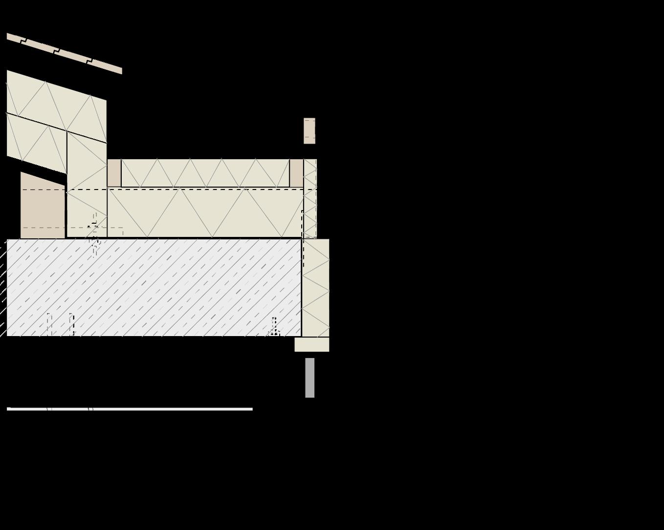
ENVELOPE AND FIRST FLOOR SLAB CONNECTION
1. 500/1200 mm reinforced concrete upstand beam on ground floor ceiling slab
2. 200 mm fibreglass insulation
3. 120 mm fibreglass insulation
4. 300 mm and 60 mm insulation
5. Vapour/damp proof barrier
6. 100/50/80 mm steel RHS first floor facade fin bracing
7. 30 mm metal grating on 60/30/8 mm steel h-profile frame 8. Triple thermal glazing 8 mm + 14 mm cavity + 6 mm + 14 mm cavity + 25,3 mm lam. safety glass with vertical silicone caulk joint 9. 17,5 mm lam. safety glass adhesively bonded to 32/70 mm aluminium profile 10. 50 mm gravel fill
11. 150/200 mm metal profile frame 12. Soil for vegetation
3. JUNCTION DETAILS (1:5, 1:20 2D DRAWINGS)


SCALE 1:25
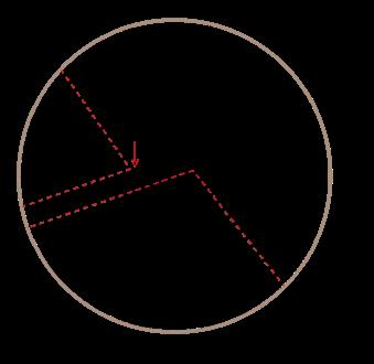
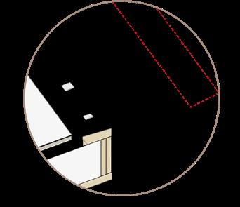
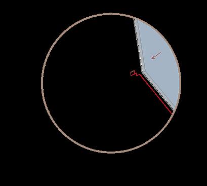
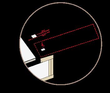
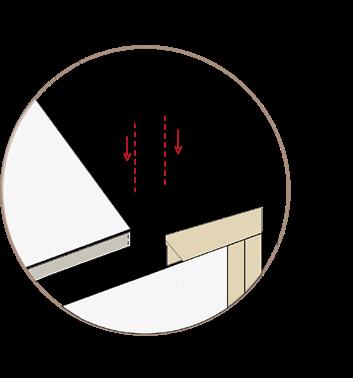
3.1 WALL TO ROOF INTERFACE
Element
CHANGE OVER TIME
Although the design office and IOC prioritised the flexibility since the early design process, it is likely that building lifespan will be shorter as assumed (or that it will require renovation) due to the longevity of chosen materials. The concrete slabs and walls are not likely to be affected due to the long estimated lifespan (estimated 50-100 years), aluminium fins and frame are estimated to last for 60-80 years, furthermore they can be recycled after. Yet the triple glazed panels can be easier affected by weather conditions, damp and overall usage ending in estimated longevity of 20-30 years. At this moment such panels are the most sustainable choice, but in several decades they can result in very expensive maintenance costs.
Envelope Build Up
(KEY ELEMENTS)

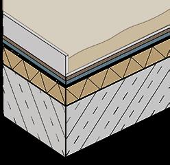
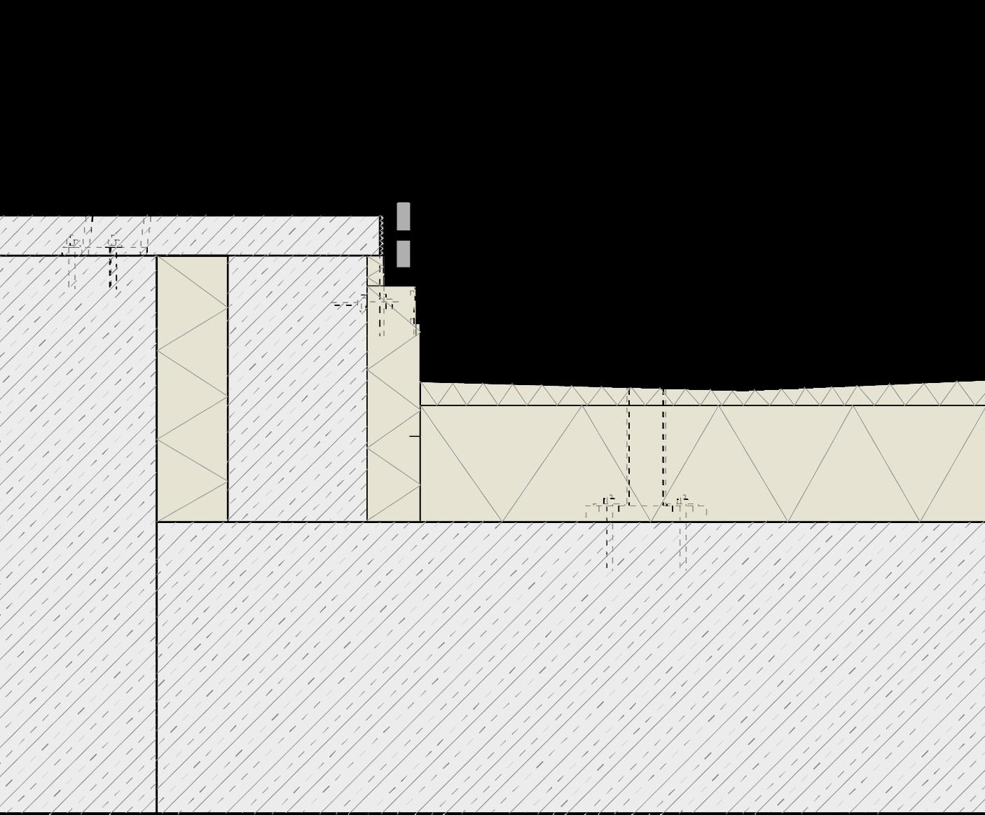
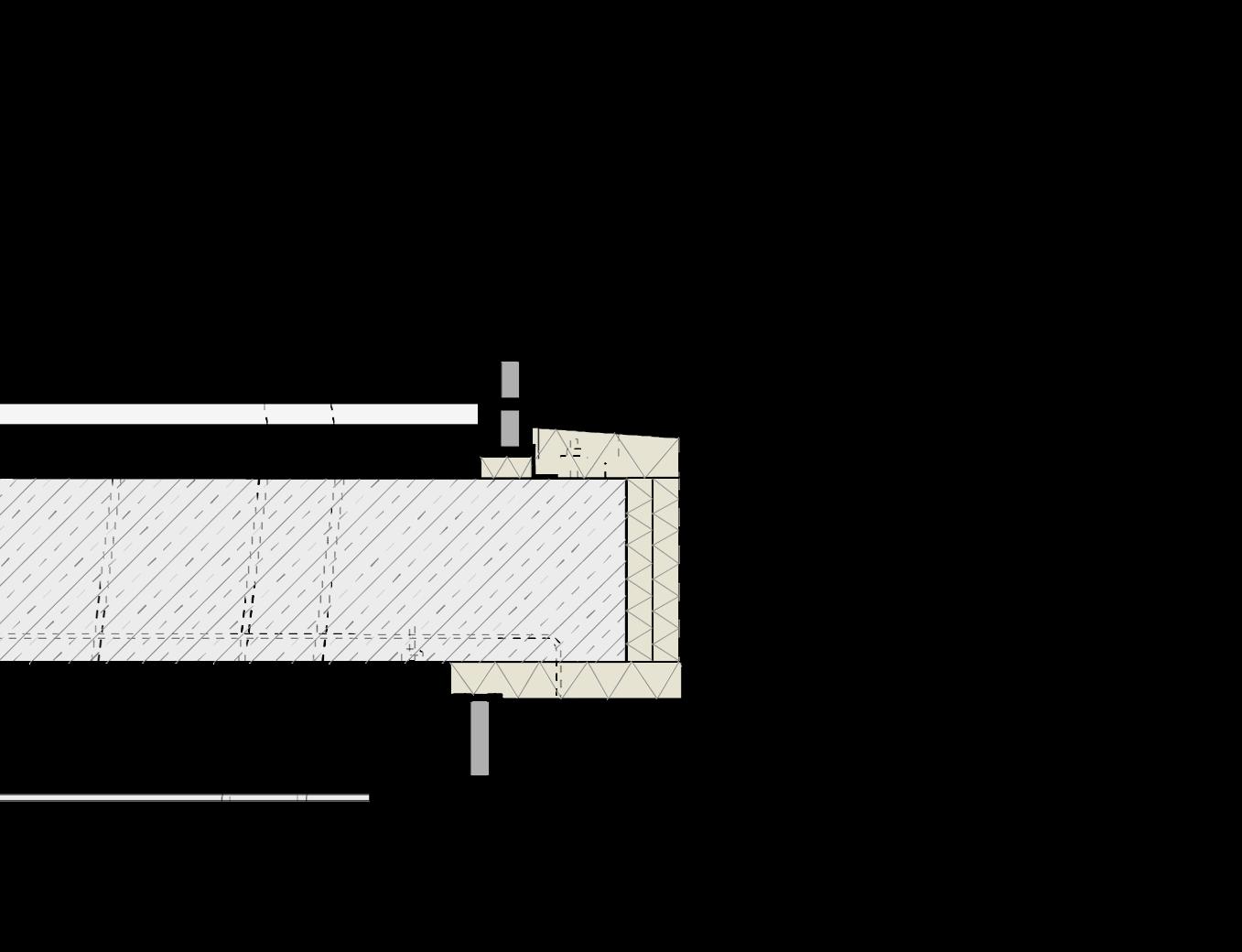
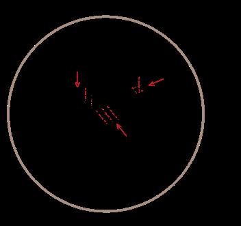
3.2 FLOOR SLAB TO EXTERNAL WALL DETAIL
+ 3.3 WINDOW DETAILS (HEAD + CILL) - no openable windows within structure
1. Inclined columns (primary structure) The layout of the suspended structure follows the sequence of 1.35 designated by inclined columns.
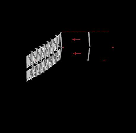
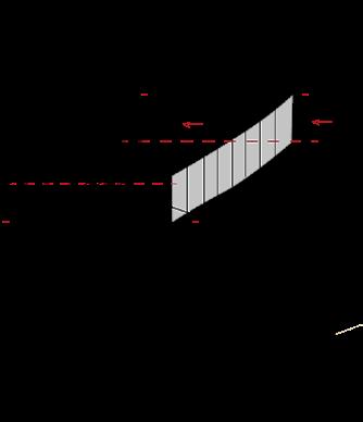
2. First layer of triple glazed panels.
3. RHS steel bars - protruding elements shape triangular, supporting frame for vertical fins and metal grating.
4. Aluminium fins - interconnected vertical plates follow the inclination of internal columns creating organic facade. They bond the steel frame at the top and bottom of each facade panel.
5. Metal grating - provides space for envelope maintenance.
6. Second layer of triple glazed panels - aluminium frames simplify the assembly process, additional layer of glazing contributes to the acoustics and thermal performance of facade.
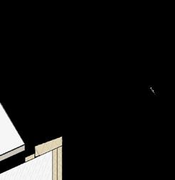
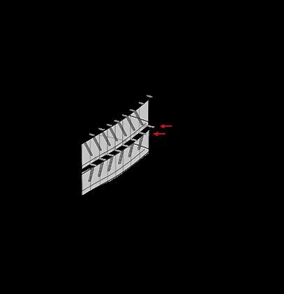
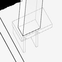
2.2 ENVELOPE ASSEMBLY (SEQUENTIAL THUMBNAILS)
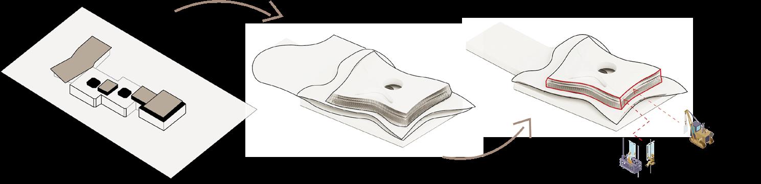
with
3.3 EXTERNAL WALL TO GROUND SLAB DETAIL
32/70 mm aluminium profile
1. 25 mm ceramic floor finish
2. 50 mm floor finish (probably thermal construction board consisting of polystyrene, glass fibre and cement based mortar)
3. 100 mm cavity with steel support bolts
4. 350 mm pre-stressed reinforced concrete ceiling slab
5. Suspended ceiling system: soundproofing, ventilation, loudspeakers, fire alarm, lighting 90/90 mm aluminium module
6. 450/55/2 mm aluminium sheet metal cladding for steel RHS profiles
7. 30 mm metal grating on 60/30/8 mm steel h-profile frame 8. 60/100 mm metal H- frame with 40/80 mm concrete blocks mounted into 20/100 mm steel bars
9. 80 mm and 60 mm fibreglass insulation fill 10. Aluminium clad profile
11. 12–18 mm silicone joint
12. 100/150 mm and 50/100 mm steel connectors bolted to horizontal aluminium bar 13. 200/120/16 mm steel RHS column: hollow, concrete fill or solid, 1350 mm off-centre
1. 500/1200 mm reinforced concrete upstand beam on ground floor ceiling slab
2. 200 mm fibreglass insulation
3. 120 mm fibreglass insulation 4. 300 mm and 60 mm insulation
5. Vapour/damp proof barrier
6. 100/50/80
1. Visual and maintenance comfort and efficiency
2. Improved thermal performance
3. Floor boards support system + structural integrity 4. Primary, loadbearing structure
5. Maintenance and services space 6. Facade support system joinery for glazed panels + improved facade stability through interconnection of aluminium fins.
7. Maintenance space + shading (sun glare protection)
8. Secondary structure; joinery element between primary structure and envelope.
9. Provision of thermal comfort and efficiency
10. Weather protection
11. Triple glazing stability and sealing - protection from moisture
12. Flexible, structural support system for metal grating
13. Primary structure element - loadbearing column
1. Primary structure loadbearing components
2. Provision of thermal comfort and efficiency
3. Provision of thermal comfort and efficiency
4. Provision of thermal comfort and efficiency
5. Vapour and damp protection
6. Bracing for first floor aluminium fins - secondary structure support system
7. Support structure for suspended facade - helps with bearing the facade loads and provides stability + space for maintenance
8. Thermal, acoustic comfort, provision of natural light, moisture resistance
9. Thermal, acoustic comfort, provision of natural light, moisture resistance
10. Protection of the damp/ vapours membranes beneath.
11. Structural barrier for greenery
12. Vegetation
