
5 minute read
Case Study 3 Olympic House in Lausanne


Year of completion: 2019
1. KEY DESIGN PARAMETERS
Advertisement
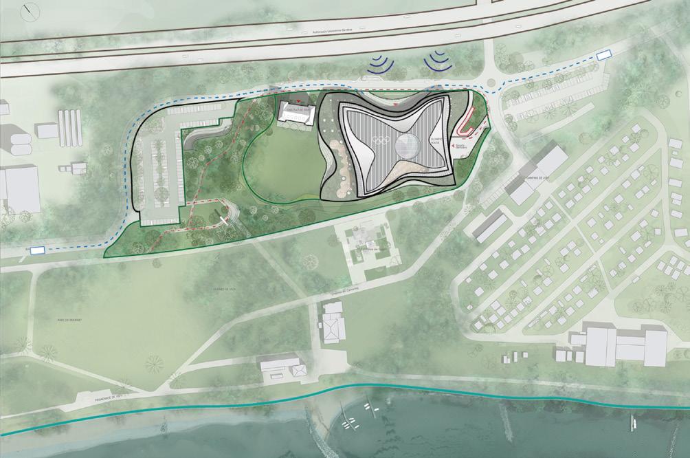
LOCATION + SITE
Lausanne - site location
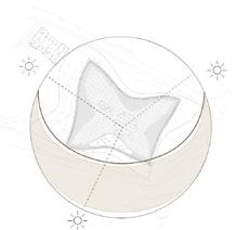
PATHS
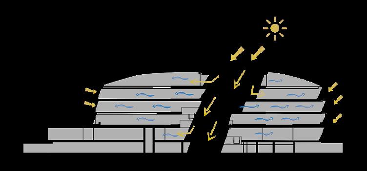
• Sunlight is evenly distributed over the year, as there is no ‘barrier’ from the southern part of site. • Building positioning and concave facade ensures maximised sunlight penetration.
SUSTAINABLE LAND USE AND ECOLOGY
The project retains existing natural features through careful treatment of the existing park and enhancement of greenery continuation through green roof on lower floor. The soil on site was initially proofed to be polluted, thus it was removed and cleaned before construction started. The building priorities future re-use of structure and site, through flexible arrangement of internal/ external spaces and provision of multifunctional areas. Additionally, some of structural elements were recycled from previous building’s demolition waste (concrete aggregate).
• The building responds to the demand of local context and provides multi-purpose office and meeting spaces, whose arrangement can be easily adapted to users.
• The project provides green areas such as; green roof, terraces and landscaping which helps maintaining site’s biodiversity.
Architects: 3XN, IttenBrechbühl
Structural engineers: Ingeni Facade offices: Frener & Reifer
2. STRUCTURAL DESIGN STRATEGIES
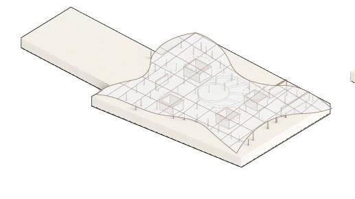
2.1 ISOMETRIC VIEW
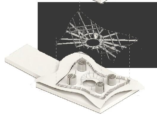

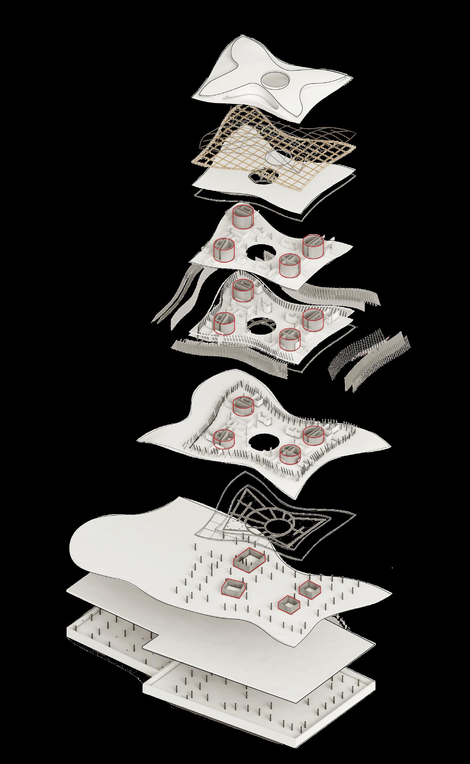
ROOF
PRIMARY STRUCTURE
Thin steel frame supporting timber frame and aluminium cladding. Timber frame constructed from 180/280 timber beams and 25/50 mm timber battens. Concrete slab supported by radial bracing in central, atrial part.
UPPER FLOORS
PRIMARY STRUCTURE
• Main loadbearing structure: cylindrical, concrete cores.
• 200/120/16mm inclined columns arrayed along slab perimeter with 1.35m distance, following inclination of no more than 30 ºC.
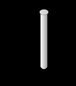
• Steel columns of (estimated) 300mm diameter spread unevenly over the plan. (Their positioning was calculated using computational software)
• 350mm pre-stressed reinforced concrete slab
• Steel beams with radial bracing in the central area. - Support of atrial staircase.
GROUND FLOOR
PRIMARY STRUCTURE

• Loadbearing concrete walls (located under the cylindrical cores)
SUSTAINABLE CONNECTIVITY AND TRANSPORT
Project promotes more ecological transport, through proximity of public transport links.
• The building priorities green transport through bicycle/pedestrian paths included in the landscaping, as well as provision of bicycle stands.
• The project includes amenities for active commuters such as showers, lockers or rooms for personal storage.
SUSTAINABLE COMMUNITIES AND SOCIAL VALUE

• The identity of the building is expressed through dynamic form that responds to athlete’s movement and key values of organisation: openness (transparency of structure), unity (round unity stairs), fairness (solar panels in for of peace dove).

Social integration is enhanced through open layout and outdoor and indoor recreation space (wellness centre).
Provision of public realm pedestrian paths stimulate outdoor interactions.
• The programme includes several private rooms such as private offices, storage rooms, enclosed meeting areas.
• Locating offices and meeting areas on the upper floors adds to safety, as public accessible areas are located on the ground floor.
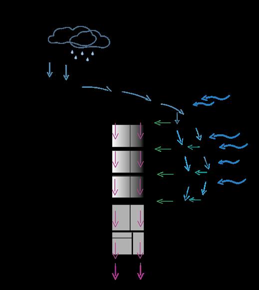
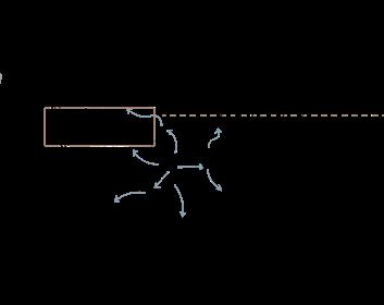
Load Paths


3. BUILDING FABRIC + CONSTRUCTION

3.1 ISOMETRIC VIEW ELEMENTAL BUILD-UPS + ZONES
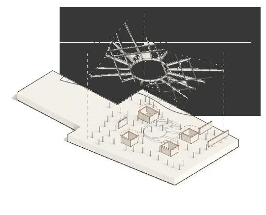
ROOF STRUCTURE
Lightweight roof structure enabled design of an organic shape without massive addition to structural loads.

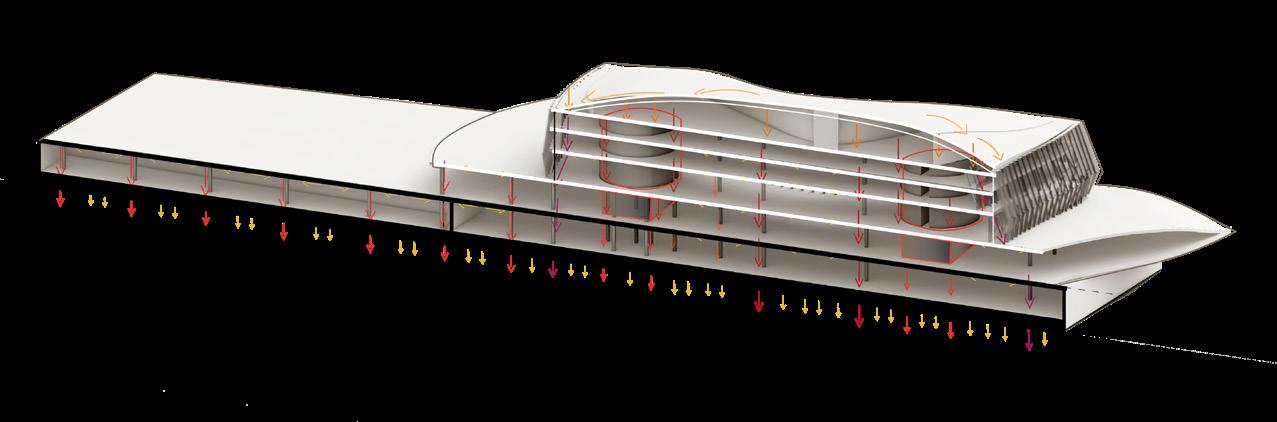
Concrete cores bear the majority of the structural loads and transmit them to the foundation slab. Steel columns spread unevenly in the plan help with distribution of live loads and support concrete slabs. Angled columns along the perimeter provide even lateral loads distribution and transmit loads of cantilevered areas of concrete slabs.
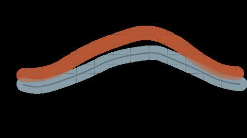
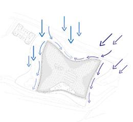
LATERAL LOADS
Lateral loads imposed on roof and facade are transmitted through concrete slab to primary loadbearing elements - concrete cores and angled columns on perimeter.
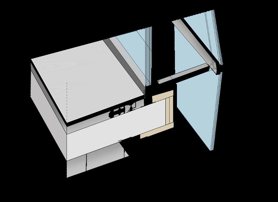
SECONDARY STRUCTURE
Envelope assembly:
• Inclined columns
• Vertical, triple glazed panels
• Suspended facade: aluminium fins, frame fitted with triple glazed panels
Lateral Loads
3.2 CONSTRUCTION STRATEGIES SEQUENTIAL THUMBNAILS
1. Excavation of soil, removal of polluted soil for cleaning.
The envelope design was determined by the complex shape of structure, which aimed to aesthetically present values of IOC - this the organic envelope refers to the dynamic, athlete’s movement.


Primary structure - inclined, steel columns mounted into rc floor slab.
Triple glazed panels
Aluminium frame - supporting structure for suspended facade
2. Preparation of ground for raft concrete foundation.
3. Construction of primary structure on basement level: loadbearing columns and (probably) steel beams - bracing.
Facade design follow layout of inclined columns with 1.35m distancing.
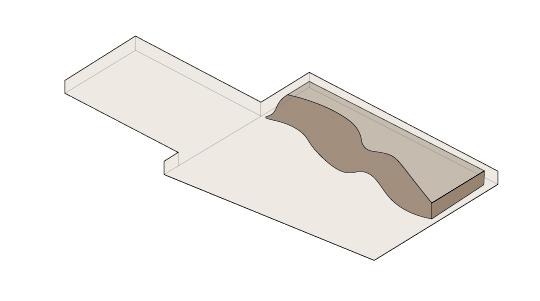
CANTILEVERED FLOOR
According to the architects, 9m floor slab structure from perimeter is cantilevered. Such deci sion aimed to ensure flexi bility of working spaces.
• Cylindrical steel columns with (estimated) 300 diameter and strengthened by diagonal supports.
FOUNDATION:
• Reinforced concrete slab foundation of (estimated) 1200mm depth
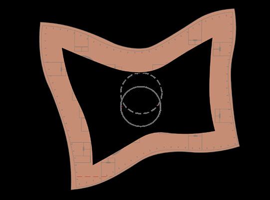
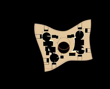
2.2 GENERAL ARRANGEMENT - PLAN, ELEVATION, SECTION

The layout of the plan is open and does not rely on structural grid. The columns are placed irregularly, similarly to rectangular partition walls, which allows flexibility of the structure; probably partition walls are movable or temporary to allow transformation office space into conference or individual rooms.
Some of the partition walls - adjacent to the perimeter - follow 2.7m grid designated by 1.35m column spacing.
SECTION + SLABS AND CEILING HEIGHTS
INDIVIDUAL OFFICE ROOM
Vertical, aluminium fins
Metal grating (for maintenance and shading)
Second layer of triple glazed panels (customised) in aluminium frames
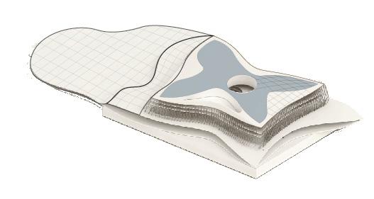
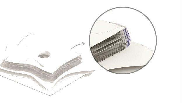
Envelope And Slab Connection
Double skin facade with triple glazing provides acoustic comfort (noise was the main issue in previous building.)
Moreover it allows more daylight into interior, increasing comfort of users and reducing demand for artificial lighting.
4. Construction of ground floor reinforced concrete walls (loadbearing structure ), steel beam frame and temporary framework for concrete slabs (probably cast on site with temporary framework).
5.Temporary framework for concrete slab cast.
6 Construction first floor slab - reinforced concrete edges of structure slope down to the ground level, bearing the loads of upper floors.
7. Concrete cores with its loadbearing walls are constructed and supported by 13 columns on each floor.
CONFERENCE ROOMS
INDIVIDUAL OFFICE ROOM
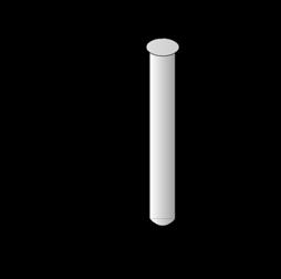
Four concrete core of (estimated) diameter of 10,8m were designed in similar manner: three of them include toilets, staircases and service areas.
The fourth concrete core does not include toilets but contains staircase, lifts and additional service shafts. In the terms of dimensions, it relies on the same 10,8m module.

OPEN LAYOUT + ATRIUM
Dimensions of several, modular units that combine individual and group office space.
The layout follows primary structure inclined columns on the slab perimeter and facade panels.
Open layout offers not only flexibility of the space, but also provides natural ventilation thanks to undisrupted airflows from atrium.
Aluminium cladding and frame result in lower maintenance, better moisture resistance and sustainability - 95% of aluminium used can be recycled.
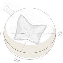
Envelope And Ground Floor Connection
Concrete slabs result in high thermal mass, which helps with efficient heating and cooling of structure.
Furthermore, choosing concrete enabled re-use of concrete aggregate of pre-existing office structure.
Placing green roof on the first floor slab aimed into creating a visual connection between building’s and park’s greenery.
Parametric facade structure was designed using BIM software and computational design, which led to the necessity of customisation of glazed panels and aluminium frames.
Such solution resulted in visually impressive, unique design, yet it was probably more expensive and technically unnecessary feature (the facade could have been standardised for lower costs and more efficient construction).
8. Second and third floor primary construction is built; this includes concrete cylinders, supporting columns and inclined columns.
9. Roof construction.
10. Simultaneously first layer of envelopeglazed panels are mounted starting from ground floor.
11. Aluminium fins are mounted to the joints fixed to the facade.
12. A the same time surrounding landscape is filled with necessary layers of foundation for vegetation growth.
13. Assembly of the envelope: fixing aluminium framed glazed panels into suspended frame.
