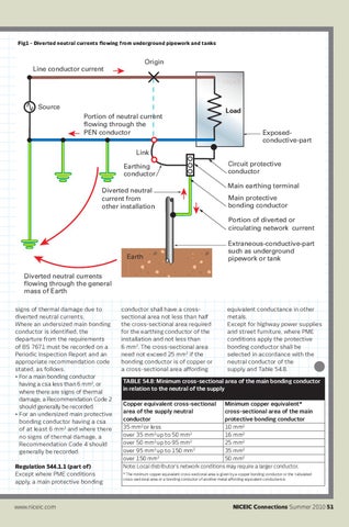
Fig1 - Diverted neutral currents flowing from underground pipework and tanks
Origin Line conductor current FAULT
Source Portion of neutral current flowing through the PEN conductor
Load LOAD Exposedconductive-part
Link Earthing conductor Diverted neutral current from other installation
Circuit protective conductor Main earthing terminal Main protective bonding conductor Portion of diverted or circulating network current
Earth
Extraneous-conductive-part such as underground pipework or tank
Diverted neutral currents flowing through the general mass of Earth signs of thermal damage due to diverted neutral currents. Where an undersized main bonding conductor is identified, the departure from the requirements of BS 7671 must be recorded on a Periodic Inspection Report and an appropriate recommendation code stated, as follows. • For a main bonding conductor having a csa less than 6 mm2, or where there are signs of thermal damage, a Recommendation Code 2 should generally be recorded. • For an undersized main protective bonding conductor having a csa of at least 6 mm2 and where there no signs of thermal damage, a Recommendation Code 4 should generally be recorded. Regulation 544.1.1 (part of) Except where PME conditions apply, a main protective bonding
www.niceic.com
conductor shall have a crosssectional area not less than half the cross-sectional area required for the earthing conductor of the installation and not less than 6 mm2. The cross-sectional area need not exceed 25 mm2 if the bonding conductor is of copper or a cross-sectional area affording
equivalent conductance in other metals. Except for highway power supplies and street furniture, where PME conditions apply the protective bonding conductor shall be selected in accordance with the neutral conductor of the supply and Table 54.8.
TABLE 54.8: Minimum cross-sectional area of the main bonding conductor in relation to the neutral of the supply Minimum copper equivalent* Copper equivalent cross-sectional cross-sectional area of the main area of the supply neutral protective bonding conductor conductor 35 mm2 or less 10 mm2 2 2 16 mm2 over 35 mm up to 50 mm 2 2 over 50 mm up to 95 mm 25 mm2 2 2 over 95 mm up to 150 mm 35 mm2 2 over 150 mm 50 mm2 Note: Local distributor’s network conditions may require a larger conductor. * The minimum copper equivalent cross-sectional area is given by a copper bonding conductor or the tabulated cross-sectional area or a bonding conductor of another metal affording equivalent conductance.
NICEIC Connections Summer 2010 51