• Controlling arcing – because the supply does not pass through 0 a DC circuit can maintain an arc more readily than that of a circuit supplied from an AC source. • Lack of familiarity – wrong choices for switching and overcurrent protection may occur. • Difficulty in converting between voltage levels – power electronic converters are necessary.
Fig 2 2-wire and 3-wire arrangement
Conductor arrangement and system earthing
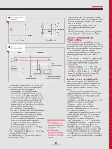
Fig 3 A short circuit in a TN-S DC arrangement Source
Installation L+ Isc
PEL
L(PE) Protective conductor
Optional application of a battery
Equipment in installation Earthing of system
The benefits of the use of DC in low-voltage DC (LVDC) installations include amongst others: • Reduction in power consumption. • The use of DC removes the need for individual AC-DC power supplies (switch mode power supplies) for individual items of current-using equipment. Whilst it is still remains necessary to convert between DC voltage levels, the losses associated with this conversion are lower than for equivalent switch mode power supplies. • No consideration of power factor. • No need to consider reactive power as there is no capacitive or inductive reactance – although there is the potential for energy storage in capacitors and inductors. • In AC circuits reactance must be considered to accurately determine voltage drop in larger conductors. In DC circuits only resistance need be considered and, therefore, there is a reduction in volt drop. • Fewer components required. • More integration with DC systems – PV, energy storage, EV charging etc. The disadvantages of the use of DC include, amongst other things:
Exposed-conductive-parts
1 PEL – a conductor combining the functions of both a protective earthing conductor and a line conductor 2 PEM – a conductor combining the functions of both a protective earthing conductor and a mid-point conductor
Whilst Regulation 312.1.2 details the currentcarrying conductors in DC circuits (Fig 2), it is to Appendix 9 that reference should be made when determining the nature of DC earthing systems. Strictly speaking, both PEL1 and PEM2 conductors are not live conductors although they carry operating current (see note to 312.1.2). A PEL two-wire DC circuit has a single voltage available, L+ to L- (U0), whilst a PEM threewire arrangement allows for three possible arrangements: • a positive voltage (L+ to M or PEM) (U0), • a negative voltage (L- to M or PEM) (-U0) and • a combined higher voltage (L+ to L-) (2U0). Appendix 9 of BS 7671 details the earthing systems available for DC supplies.
Short circuit and earth fault paths Short circuit and earth fault conditions are well understood in AC systems. However, the definition of a short circuit found in Part 2 of BS 7671 applies to both AC and DC circuits, that is, ‘An overcurrent resulting from a fault of negligible impedance between live conductors having a difference in potential under normal operating conditions’. Equally, an earth fault current applies to both AC and DC circuits, and is defined as: ‘A current resulting from a fault of negligible impedance between a line conductor and an exposed-conductive-part or a protective conductor’. The following images highlight the potential current paths for both short circuit and earth fault conditions in a DC circuit for both a PEL arrangement and a PEM arrangement. This arrangement is a TN-S DC system with an earthed line conductor L- separated from the protective conductor throughout the installation (Fig 3). It is based on Appendix 9 and has a separate protective conductor (PE) throughout the installation. The short circuit occurs between the live conductors although one of those live conductors is also connected to earth.
49 S U MME R 2 018
48-50 DC in BS 7671.cc.indd 49
21/06/2018 11:29