Anchoring and Fastening Systems for Concrete and Masonry
Acceptable Hole Diameter
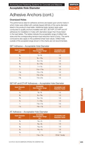
Adhesive Anchors (cont.) Oversized Holes The performance data for adhesive anchors are based upon anchor tests in which holes were drilled with carbide-tipped drill bits of the same diameter listed in the product’s load table. Additional static tension tests were conducted to qualify anchors installed with SET, SET-XP®, ET-HP® and AT adhesives for installation in holes with diameters larger than those listed in the load tables. The tables indicate the acceptable range of drilled hole sizes and the corresponding tension-load reduction factor (if any). The same conclusions also apply to the published shear load values. Drilled holes outside of the accepted range shown in the charts are not recommended.
SET Adhesive – Acceptable Hole Diameter Acceptable Hole Diameter Range (in.)
Acceptable Load Reduction Factor
3⁄8
1⁄2 – 3⁄4
1.0
1⁄2
5⁄8 – 1 5⁄16
1.0
5⁄8
3⁄4 – 1 1⁄8
1.0
3⁄4
7⁄8 – 1 5⁄16
1.0
7⁄8
1 – 1 1⁄2
1.0
1
1 1⁄8 – 1 11⁄16
1.0
1 1⁄8
1 1⁄4 – 1 7⁄8
1.0
1 1⁄4
1 3⁄8 – 2 1⁄16
1.0
1 3⁄8
1 1⁄2 – 2 1⁄4
1.0
Insert Diameter (in.)
Acceptable Hole Diameter Range (in.)
Acceptable Load Reduction Factor
1⁄2
5⁄8 – 3⁄4
1.0
5⁄8
3⁄4 – 15⁄16
1.0
3⁄4
7⁄8 – 1 1⁄8
1.0
7⁄8
1 – 1 5⁄16
1.0
1
1 1⁄8 – 1 1⁄2
1.0
1 1/4
1 3/8 – 1 7/8
1.0
Insert Diameter (in.)
Appendix
SET-XP and ET-HP Adhesives – Acceptable Hole Diameter
AT Adhesive – Acceptable Hole Diameter Insert Diameter (in.)
Acceptable Hole Diameter Range (in.)
Acceptable Load Reduction Factor
3⁄8
7⁄16 – 1⁄2
1.0
1⁄2
9⁄16 – 5⁄8
1.0
5⁄8
11⁄16 – 3⁄4
1.0
3⁄4
13⁄16 – 7⁄8
1.0
7⁄8
1
1.0
1
1 1⁄16 – 1 1⁄8
.75 for 1 1⁄8 only
S-A-PG16 © 2016 SIMPSON STRONG-TIE COMPANY INC.
225