TTCI R&D The mongoose versus the snake:
Rail head wear versus rail head fatigue by G. Fry, Ph.D., P.E., former director, Center for Railway Research, Texas A&M University, Transportation Technology Center, Inc., and P. Tangtragulwong, Ph.D., P.E., former graduate reserch assistant, Texas A&M University
TTCI evaluates century-old field observations that rail head fatigue cracks do not occur under certain conditions of rail head wear.
recent collaboration between Texas A&M University and the Association of American Railroads (AAR) applied analytical methods from solid mechanics to explore century-old field observations that rail head fatigue cracks do not occur under certain conditions of rail head wear. The study, conducted within the Center for Railway Research at Texas A&M University in collaboration with the AAR’s University Affiliated Laboratory program, indicates directly that the mechanisms of rail head wear disrupt the mechanisms of rail head fatigue crack formation. An operational model of the wear-fatigue interaction helps to determine the minimum rail wear rates necessary to preclude forming rail head fatigue cracks; i.e., Fatigue Crack Preventative (FCP) wear rates. In this study, “optimal” wear rates are predicted to increase the service life of a given rail under heavyaxle-loads by approximately 240 percent while completely preventing the formation of internal rail head fatigue cracks. One might imagine rail head wear as a predator that stalks, and consumes, the fatigue-damaged steel of the rail head —
much like the proverbial mongoose stalking and consuming a snake. This computational analysis requires three essential and concurrent effects be quantified and modeled. First, the process of developing internal fatigue cracks in the head of a rail requires that the steel at a critical location below the running surface be exposed to a very large number of wheel passages. Second, at the same time as the fatigue cycles are accumulating, the passage of wheels is also causing the rail head to wear down — with rail grinding operations further increasing the loss of rail head area. Third, as the head wears down, the critical fatigue location below the running surface moves down as well so that “fresher” steel is being exposed to the effects of fatigue damage accumulation. With a working model of these competing processes, another model is used to determine “optimized” rail wear rates under the constraint of preventing the nucleation and early growth of rail head fatigue cracks. Surface crack nucleation in rails can be attributed to localized plastic deformation of material close to the wheel-rail interface. By contrast, subsurface cracks nucleate at greater depth below the running surface where the material deforms elastically. 1 Note that this type of fatigue cracking can be found in heavy-axle-load lines more often than in passenger railways due to a larger accumulation of tensile residual stresses in the heavyaxle-load case. Focusing on subsurface crack nucleation in the head of thermite-welded rail and assuming various forms of pre-existing metallurgical discontinuities within the rail head 2 has shown that if residual stresses are included in the analysis, fatigue damage predicted by a multi-axial fatigue model increases significantly within the region located .39 to .59 inch (10-15 mm) below running surface. These semi-analytical predictions suggest strongly that residual stresses can play an important role in subsurface fatigue crack nucleation within the rail head. Ekberg and Kabo 3 give an overview of rolling contact fatigue (RCF) under wheel-rail contact with an emphasis on surface and subsurface crack nucleation and propagation. They suggest that RCF differs from classical fatigue behaviors because the state of stress due to rolling contact is multi-axial and non-proportional and rolling contact involves compressive loads.
A
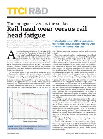
Figure 1: This figure shows a log-log plot of fatigue index versus number of cycles to failure for = 1.
www.rtands.com
Railway Track & Structures
January 2018 11