
HELIFLEX® SELECTION GUIDE
Edition 1 / 9.2023

RFS TRANSMISSION LINE SOLUTIONS
 HELIFLEX installed on The Iron Lady
EIFFEL TOWER - PARIS, FRANCE
HELIFLEX installed on The Iron Lady
EIFFEL TOWER - PARIS, FRANCE

HELIFLEX: AN INTRODUCTION Setting broadcast industry standards for decades 2 HELIFLEX AIR DIELECTRIC CABLE A full range of solutions for every application 5 SHIPPING & DRUM INFORMATION For streamlined fulfillment and delivery 12 AUTOMATIC DEHYDRATORS Essential accessory for pressurization of systems 14 ADAPTORS High-performance adaptors for flexible installation 16 CONNECTORS WITH PERFECT SEALING For easy-to-install, reliable connections 17 CASE STUDY: EIFFEL TOWER Broadcasting at one of the world’s most iconic sites 18 1 Transmission Line Solutions
TABLE OF CONTENTS RADIO FREQUENCY SYSTEMS
HELIFLEX® BY AN RFS SPECIALIST
Gerd Bohnet, Product Line Manager Waveguide & Air Dielectric Cable at RFS talks us through the solution and how it is used.
A SIMPLE FIRST QUESTION, WHAT IS HELIFLEX®?
HELIFLEX is RFS’s portfolio of corrugated coaxial air dielectric cables. The HELIFLEX cables are air filled coaxial cables where the inner conductor is centered by dielectric spacers. This gives the RFS solution several advantages versus alternative options. The first is indicated in the name, HELIFLEX is so named due to the helix corrugation. This makes this cable flexible, allowing it to be wound onto a drum and manufactured in single long length pieces. This is the big advantage compared to rigid lines which can handle similar power but in shorter length and without any flexibility. Additionally, when compared with foam dielectric cables it has the advantage of a higher power rating due to lower attenuation at the same dimension. This gives our customers a number of benefits when they select HELIFLEX for projects.
HOW LONG HAS RFS OFFERED THIS TYPE OF SOLUTION AND HOW HAS IT EVOLVED?
RFS began production of HELIFLEX in 1951 and has continued to evolve its portfolio of this product over the last 70 years. We are now able to offer larger cable sizes up to 8” and 9” allowing us to cater for a great range of applications. In addition to the cables themselves, we have also committed to developing a range of essential accessories together with selected suppliers to improve the deployment process and address the needs of our customers.
CAN YOU GIVE AN EXAMPLE OF AN APPLICATION USING HELIFLEX?

The main application for HELIFLEX cables is in the broadcast sector, specifically in applications where there is a need to transport high power signals from the transmitter to the antenna with lowest possible attenuation and signal distortion. The solutions are not limited to broadcast applications, but can be used for all high power application where attenuation is an issue.
HELIFLEX HAS BEEN DEPLOYED IS USED ALL OVER THE WORLD, HOW DO YOU ENSURE CUSTOMERS GET THE MOST OUT OF THE SOLUTION?
One of the real strengths for customers selecting HELIFLEX is that we are able to provide both the cable and the required accessories to ensure an efficient and effective solution. With dedicated accessories like clamps, grounding kits, and connectors which are optimized to our cables the customer minimized the risk of performance loss during installation and operation over the years.
At RFS, we take great pride in the fact our solutions are built to last. As an example, RFS delivered 9” cable for the at the Wertachtal transmitter site in Bavaria, Germany to support broadcasting for the 1972 Olympic Games in Munich. From 1972 to 2013 this was the biggest shortwave broadcasting facility in Europe and is still operating 50 years later without performance degradation, demonstrating a solution that is still standing the test of time.
WHAT DOES THE FUTURE HOLD FOR THE HELIFLEX PORTFOLIO?
As long as radio stations are installed, there will be a need for cable. The HELIFLEX option helps to guarantee an efficient installation with highest possible performance. RFS is one of only a handful of manufacturers specializing in this style of cable and our heritage in the space allows us to develop best in class solutions for an ongoing challenge faced by broadcasters.
This guide looks at the full HELIFLEX portfolio of cables and accessories, with case study examples to help identify the best solution for any deployment.GERD BOHNET
2 Transmission Line Solutions
Product Line Manager Waveguide, Air Dielectric Cable & Accessories
HELIFLEX: SETTING THE STANDARD FOR DECADES
HIGH PERFORMANCE WITH LOW ATTENUATION
HELIFLEX is a high-performance cable with a design that offers the lowest possible attenuation and signal distortion. This allows HELIFLEX solutions to have a higher power rating compared to foam dielectric cables of the same dimension, making it ideal for broadcast applications needing to transport high-power signals from the transmitter to the antenna.

EASY INSTALLATION
As the flexible cable can be shipped as long single pieces, the deployment process is streamlined. The cable is simple for field engineers to install and the potential infrastructure weaknesses that come from cable joins are removed.
SIMPLE LOGISTICS
The flexibility of the solution allows longer pieces to be wound onto a drum. This facilitates easier and more compact transportation for lower cost and lower environmental impact.
RUGGEDIZED
The solution is designed for outside deployment and to withstand severe weather conditions. HELIFLEX can be deployed on-site for decades with no impact on its ongoing performance.
COMPLETE SOLUTION
In addition to the cables themselves, RFS offers a complete range of essential accessories; clamps, grounding kits, and connectors. They are designed to minimize the risk of performance loss during installation and ensure operation without degradation for the life of the cables over the years.
ON AIR HELIFLEX®
HELIFLEX cables are airfilled coaxial cables where the inner conductor is centered by dielectric spacers. Designed and patented by RFS over 70 years ago, this style of cable has become the de-facto industry standard, with RFS’s premium HELIFLEX
solutions installed across the globe. Available in cable sizes between 7/8” and 6 1/8” (larger sizes available on request), the unique helix corrugation makes for a flexible and versatile cable that offers big advantages for a range of applications.
Transmission Line Solutions
HELIFLEX AIR DIELECTRIC COAXIAL CABLE
HCA 7/8" Series: 3 GHz
PRODUCT SPECIFICATIONS
Retardant
Specifications
RELATED
TEMPERATURE SPECIFICATIONS STANDARD JACKET J FLAME RETARDANT JACKET JFN
* Premium return loss cable available. Contact Sales for options in your specific frequency band.
Meets the requirements according to: IEC60754-1, IEC60754-2
The jacketing meets the testing requirements of Underwriters Laboratories UL 1666, and qualifies for the NEC CATVR type rating code (NEC Section 820-51(b) Type CATVR- NEC 1996) as well as IEC 60332-1
MECHANICAL
Model Number Type
WF-78 Wall Feed Through for Cable HCA78/LCF78 Single Entry Kit (without Feed Through Plate)
EAR-78 Grounding Kit for HELIFLEX Cable HCA78
HCH-78-1L4 Hanger for HELIFLEX Cable HCA78 Cable Angle Iron 40 mm (1.575in)
HCH-78-1R Hanger for HELIFLEX Cable HCA78 Cable Flat Iron 6 - 12 mm (0.24 - 0.47in)
HCH-78-1C Hanger for HELIFLEX Cable HCA78 Cable Anchor Bar 18 - 22 mm (0.7 - 0.9in)
HOIST1-78L Hoisting grip, open, LCF/UCF/HCA78, E100, E105, EO19
MODEL NUMBER JACKETING OPTION HCA78-50J HELIFLEX 7/8in Low Loss Air Dielectric Cable Standard Jacket intended for Outdoor Usage HCA78-50JB HELIFLEX 7/8in Low Loss Air Dielectric Cable Standard Jacket intended for Outdoor Usage, Self-Healing Jacket HCA78-50JFN HELIFLEX 7/8in Low Loss Air Dielectric Cable Flame retardant / Halogen free Jacket
ORDERING INFORMATION GENERAL SPECIFICATIONS Nominal Size inch 7/8 Jacket Color Black Jacket Material Polyethylene, PE Diameter Over Jacket mm 25 Cable Volume L/m 0,34 Cable Weight kg/m 0,68
PRODUCTS Model Number Type NM-HCA78-020 Connector for HELIFLEX Cable HCA 7/8-50, N Male (Plast2000 sealing) NF-HCA78-020 Connector for HELIFLEX Cable HCA 7/8-50, N Female (Plast2000 sealing) 716M-HCA78-020 Connector for HELIFLEX Cable HCA 7/8-50, 7-16 Female (Plast2000 sealing) 716F-HCA78-020 Connector for HELIFLEX Cable HCA 7/8-50, 7-16 Male (Plast2000 sealing) 78EIA-HCA78-019 Connector for HELIFLEX Cable HCA 7/8-50, 7/8 EIA (O-Ring sealing) 158EIA-HCA78-020 Connector for HELIFLEX Cable HCA 7/8-50, 1 5/8 EIA (Plast2000 sealing) 78EIA-CE-002 Coupling Element for 7/8 EIA Connectors 158EIA-CE-002 Coupling Element for 1 5/8 EIA Connectors ELECTRICAL SPECIFICATIONS Impedance ohm 50 +/-0.5 Maximum Frequency GHz 3 Min. Return Loss (Max VSWR) dB (VSWR) 20.8 (1.2) typical * Velocity % 93 Attenuation dB See cable’s model datasheet Peak Power Rating KW 73 RF Peak Voltage V 2700 Jacket Spark V RMS 8000 Phase Stabilized Phase stabilized and phase matched cables and assemblies are available upon request. High Power performance High Power cable is available upon request.
SPECIFICATION Minimum Bending Radius, Single Bend mm 100 Minimum Bending Radius, Repeated Bend mm 250 Bending Moment Nm 27 Tensile Strength N 1600 Recommended / Maximum Clamp Spacing m 0.5 / 0.9
Installation °C -40 to +60 -25 to +60 Storage °C -70 to +85 -70 to +85 Operation °C -50 to +85 -50 to +85 Flame
Jacket
4 Transmission Line Solutions
Transmission Line Solutions
HELIFLEX AIR DIELECTRIC COAXIAL CABLE
HCA 1-1/8" Series: 3 GHz
ORDERING INFORMATION
MODEL NUMBER JACKETING OPTION
HCA118-50J HELIFLEX 1 1/8in Low Loss Air Dielectric Cable Standard Jacket intended for Outdoor Usage
HCA118-50JB HELIFLEX 1 1/8in Low Loss Air Dielectric Cable Standard Jacket intended for Outdoor Usage, Self-Healing Jacket
HCA118-50JFN HELIFLEX 1 1/8in Low Loss Air Dielectric Cable Flame retardant / Halogen free Jacket
PRODUCT SPECIFICATIONS
GENERAL SPECIFICATIONS
Flame Retardant Jacket Specifications
+60 -25 to +60
Meets the requirements according to: IEC60754-1, IEC60754-2
RELATED PRODUCTS
Model Number Type
The jacketing meets the testing requirements of Underwriters Laboratories UL 1666, and qualifies for the NEC CATVR type rating code (NEC Section 820-51(b) Type CATVR- NEC 1996) as well as IEC 60332-1
158EIA-HCA118-001 Connector for HELIFLEX Cable HCA 1 1/8-50, 1 5/8 EIA (Plast2000 sealing)
158EIA-CE-002 Coupling Element for 1 5/8 EIA Connectors
HCH-118-1L4 Hanger for HELIFLEX Cable HCA118 Cable Angle Iron 40 mm (1.575in)
HCH-118-1R Hanger for HELIFLEX Cable HCA118 Cable Flat Iron 6 - 12 mm (0.24 - 0.47in)
HCH-118-1C Hanger for HELIFLEX Cable HCA118 Cable Anchor Bar 18 - 22 mm (0.7 - 0.9in)
RSB-118 RSB-Clip for HCA 118
RSB-STRAP RSB Straptite for tube mounting L=30m
RSB-310 RSB Cleat for RSB Clip
* Premium return loss cable available. Contact Sales for options in your specific frequency band.
Model Number Type
RSB-315 RSB Clamping plate for anchor bar
RSB-FAST RSB Fastener for straptite
HOIST1-114L Hoisting grip, open, UCF/LCFS114, HCA118, E70, E78, EO15
FTOOL-B118400 Basic Tool for HCA 118-50 to 400-50 (need FDIE-B***)
FDIE-B118 Flaring die for the Basic Tool HCA 118-50
Nominal Size inch 1 1/8 Jacket Color Black Jacket Material Polyethylene, PE Diameter Over Jacket mm 36,4 Cable Volume L/m 0,6 Cable Weight kg/m 1,1
ELECTRICAL SPECIFICATIONS Impedance ohm 50 +/-0.5 Maximum Frequency GHz 3 Min. Return Loss (Max VSWR) dB (VSWR) 20.8 (1.2) typical * Velocity % 92 Attenuation dB See cable’s model datasheet Peak Power Rating KW 137 RF Peak Voltage V 3700 Jacket Spark V RMS 8000 Phase Stabilized Phase stabilized and phase matched cables and assemblies are available upon request. High Power performance High Power cable is available upon request.
SPECIFICATION Minimum Bending Radius, Single Bend mm 130 Minimum Bending Radius, Repeated Bend mm 400 Bending Moment Nm 42 Tensile Strength N 2200 Recommended / Maximum Clamp Spacing m 0.5 / 0.9 TEMPERATURE SPECIFICATIONS STANDARD JACKET J FLAME RETARDANT JACKET JFN Installation °C -40 to
Storage °C -70
-70
Operation °C -50 to +85 -50
+85
MECHANICAL
to +85
to +85
to
5
HELIFLEX AIR DIELECTRIC COAXIAL CABLE
HCA 1-5/8" Series: 3 GHz
MODEL NUMBER JACKETING OPTION
HCA158-50J HELIFLEX 1 5/8in Low Loss Air Dielectric Cable Standard Jacket intended for Outdoor Usage
HCA158-50JB HELIFLEX 1 5/8in Low Loss Air Dielectric Cable Standard Jacket intended for Outdoor Usage, Self-Healing Jacket
HCA158-50JFN HELIFLEX 1 5/8in Low Loss Air Dielectric Cable Flame retardant / Halogen free Jacket
PRODUCT SPECIFICATIONS
The jacketing meets the testing requirements of Underwriters Laboratories UL 1666, and qualifies for the NEC CATVR type rating code (NEC Section 820-51(b) Type CATVR- NEC 1996) as well as IEC 60332-1
RELATED PRODUCTS
Model Number Type
716F-HCA158-001 Connector for HELIFLEX Cable HCA 1 1/8-50, 7-16 Female (Plast2000 sealing)
716M-HCA158-001 Connector for HELIFLEX Cable HCA 1 1/8-50, 7-16 Male (Plast2000 sealing)
78EIA-HCA158-001
Connector for HELIFLEX Cable HCA 1 1/8-50, 7/8 EIA (Plast2000 sealing)
158EIA-HCA158-019 Connector for HELIFLEX Cable HCA 1 5/8-50, 1 5/8 EIA (O-Ring sealing)
78EIA-CE-002 Coupling Element for 7/8 EIA Connectors
158EIA-CE-002 Coupling Element for 1 5/8 EIA Connectors
WF-158 Wall Feed Through for Cable HCA158/LCF158 Single Entry Kit (without Feed Through Plate)
EAR-158 Grounding Kit, Pre-formed Copper Strap for HELIFLEX Cable HCA158
HCH-158-1L4 Hanger for HELIFLEX Cable HCA158 Cable Angle Iron 40 mm (1.575in)
HCH-158-1R Hanger for HELIFLEX Cable HCA158 Cable Flat Iron 6 - 12 mm (0.24 - 0.47in)
* Premium return loss cable available. Contact Sales for options in your specific frequency band.
Model Number Type
HCH-158-1C Hanger for HELIFLEX Cable HCA158 Cable Anchor Bar 18 - 22 mm (0.7 - 0.9in)
CLAMP-158-S Hanger for HELIFLEX Cable HCA158 Standard
ANGLE-CLPM10 Angle Adapter for HELIFLEX Cable HCA Standard Hanger
HOIST1-158L Hoisting grip, open, LCF/HCA158, E58, E60, E65, EO11
FTOOL-B118400
FDIE-B158
Basic Tool for HCA 118-50 to 400-50 (need FDIE-B***)
Flaring die for the Basic Tool HCA 158-50
GENERAL SPECIFICATIONS Nominal Size inch 1 5/8 Jacket Color Black Jacket Material Polyethylene, PE Diameter Over Jacket mm 50,4 Cable Volume L/m 1,4 Cable Weight kg/m 1,3 ELECTRICAL SPECIFICATIONS Impedance ohm 50 +/-0.5 Maximum Frequency GHz 3 Min. Return Loss (Max VSWR) dB (VSWR) 20.8 (1.2) typical * Velocity % 95 Attenuation dB See cable’s model datasheet Peak Power Rating KW 270 RF Peak Voltage V 5200 Jacket Spark V RMS 8000 Phase Stabilized Phase stabilized and phase matched cables and assemblies are available upon request. High Power performance High Power cable is available upon request. MECHANICAL SPECIFICATION Minimum Bending Radius, Single Bend mm 180 Minimum Bending Radius, Repeated Bend mm 550 Bending Moment Nm 42 Tensile Strength N 1500 Recommended / Maximum Clamp Spacing m 0.8 / 1.2
SPECIFICATIONS STANDARD JACKET J FLAME RETARDANT JACKET JFN Installation °C -40 to +60 -25 to +60 Storage °C -70 to +85 -70 to +85 Operation °C -50 to +85 -50 to +85 Flame Retardant Jacket Specifications Meets
ORDERING INFORMATION
TEMPERATURE
the requirements according to: IEC60754-1, IEC60754-2
6 Transmission Line Solutions
ORDERING INFORMATION
MODEL NUMBER
HELIFLEX AIR DIELECTRIC COAXIAL CABLE

HCA 3" Series: 1,63 GHz
JACKETING OPTION
HCA300-50J HELIFLEX 3in Low Loss Air Dielectric Cable Standard Jacket intended for Outdoor Usage
HCA300-50JB HELIFLEX 3in Low Loss Air Dielectric Cable Standard Jacket intended for Outdoor Usage, Self-Healing Jacket
HCA300-50JFN HELIFLEX 3in Low Loss Air Dielectric Cable Flame retardant / Halogen free Jacket
PRODUCT SPECIFICATIONS
GENERAL SPECIFICATIONS
ELECTRICAL
The jacketing meets the testing requirements of Underwriters Laboratories UL 1666, and qualifies for the NEC CATVR type rating code (NEC Section 820-51(b) Type CATVR- NEC 1996) as well as IEC 60332-1
RELATED PRODUCTS
Model Number Type
318EIA-HCA300-019 Connector for HELIFLEX Cable HCA 300-50, 3 1/8 EIA (O-Ring sealing)
318EIA-CE-002 Coupling Element for 3 1/8 EIA Connectors
WF-300 Wall Feed Through for HELIFLEX Cable HCA300 Single Entry Kit (without Feed Through Plate)
EAR-300 Grounding Kit for HELIFLEX Cable HCA300
HCH-300-1L4 Hanger for HELIFLEX Cable HCA300 Cable Angle Iron 40 mm (1.575in)
HCH-300-1R Hanger for HELIFLEX Cable HCA300 Cable Flat Iron 6 - 12 mm (0.24 - 0.47in)
HCH-300-1C Hanger for HELIFLEX Cable HCA300 Cable Anchor Bar 1822 mm (0.7 - 0.9in)
CLAMP-300-S Hanger for HELIFLEX Cable HCA300 Standard
ANGLE-CLPM10 Angle Adapter for HELIFLEX Cable HCA Standard Hanger
* Premium return loss cable available. Contact Sales for options in your specific frequency band.
FTOOL-B118400
FDIE-B300
Grip open for HCA295, HCA300, E38
Tool for HCA
to 400-50 (need FDIE-B***)
die for the Basic Tool HCA 300-50
Nominal Size inch 3 Jacket Color Black Jacket Material Polyethylene, PE Diameter Over Jacket mm 76 Cable Volume L/m 3 Cable Weight kg/m 2,1
SPECIFICATIONS Impedance ohm 50 +/-0.5 Maximum Frequency GHz 1,63 Min. Return Loss (Max VSWR) dB (VSWR) 20.8 (1.2) typical * Velocity % 96 Attenuation dB See cable’s model datasheet Peak Power Rating KW 640 RF Peak Voltage V 8000 Jacket Spark V RMS 8000 Phase Stabilized Phase stabilized and phase matched cables and assemblies are available upon request. High Power performance High Power cable is available upon request.
SPECIFICATION Minimum Bending Radius, Single Bend mm 270 Minimum Bending Radius, Repeated Bend mm 760 Bending Moment Nm 145 Tensile Strength N 1800 Recommended / Maximum Clamp Spacing m 0.8 / 1.2 TEMPERATURE SPECIFICATIONS STANDARD JACKET J FLAME RETARDANT JACKET JFN Installation °C -40 to +60 -25 to +60 Storage °C -70 to +85 -70 to +85 Operation °C -50 to +85 -50 to +85 Flame Retardant Jacket Specifications Meets the requirements according to: IEC60754-1, IEC60754-2
MECHANICAL
Model
Type
Hoisting
Number
HOIST2-L08
Basic
118-50
Flaring
7 Transmission Line Solutions
ORDERING INFORMATION
MODEL NUMBER
HELIFLEX AIR DIELECTRIC COAXIAL CABLE
HCA 4" Series: 1,66 GHz
JACKETING OPTION
HCA400-50J HELIFLEX 4in Low Loss Air Dielectric Cable Standard Jacket intended for Outdoor Usage
HCA400-50JB HELIFLEX 4in Low Loss Air Dielectric Cable Standard Jacket intended for Outdoor Usage, Self-Healing Jacket
HCA400-50JFN HELIFLEX 4in Low Loss Air Dielectric Cable Flame retardant / Halogen free Jacket
PRODUCT SPECIFICATIONS
GENERAL SPECIFICATIONS
ELECTRICAL
The jacketing meets the testing requirements of Underwriters Laboratories UL 1666, and qualifies for the NEC CATVR type rating code (NEC Section 820-51(b) Type CATVR- NEC 1996) as well as IEC 60332-1
RELATED PRODUCTS
Model Number Type
318EIA-HCA400-019 Connector for HELIFLEX Cable HCA 400-50, 3 1/8 EIA (O-Ring sealing)
318EIA-CE-002 Coupling Element for 3 1/8 EIA Connectors
WF-400 Wall Feed Through for HELIFLEX Cable HCA400 Single Entry Kit (without Feed Through Plate)
EAR-400 Grounding Kit for HELIFLEX Cable HCA400
HCH-400-1L4 Hanger for HELIFLEX Cable HCA400 Cable Angle Iron 40 mm (1.575in)
HCH-400-1R Hanger for HELIFLEX Cable HCA400 Cable Flat Iron
6 - 12 mm (0.24 - 0.47in)
HCH-400-1C Hanger for HELIFLEX Cable HCA400 Cable Anchor Bar 18 - 22 mm (0.7 - 0.9in)
CLAMP-400-S Hanger for HELIFLEX Cable HCA400 Standard
ANGLE-CLPM10 Angle Adapter for HELIFLEX Cable HCA Standard Hanger
* Premium return loss cable available. Contact Sales for options in your specific frequency band.
MECHANICAL
Model Number Type
HOIST2-L09
FTOOL-E400618
FDIE-E400
FTOOL-B118400
Hoisting Grip open for HCA400, E30
Basic Tool for HCA 400-50 to 618-50 (need FDIE-E***)
Flaring die for the Basic Tool HCA 400-50 (HCA318-50)
Basic Tool for HCA 118-50 to 400-50 (need FDIE-B***)
Nominal Size inch 4 Jacket Color Black Jacket Material Polyethylene, PE Diameter Over Jacket mm 90,5 Cable Volume L/m 5 Cable Weight kg/m 3,1
SPECIFICATIONS
ohm 50 +/-0.5 Maximum Frequency GHz 1 Min. Return Loss (Max VSWR) dB (VSWR) 20.8 (1.2) typical * Velocity % 96 Attenuation dB See cable’s model datasheet Peak Power Rating KW 940 RF Peak Voltage V 9700 Jacket Spark V RMS 8000 Phase Stabilized Phase stabilized and phase matched cables and assemblies are available upon request. High Power performance High Power cable is available upon request.
Impedance
SPECIFICATION Minimum Bending Radius, Single Bend mm 380 Minimum Bending Radius, Repeated Bend mm 890 Bending Moment Nm 215 Tensile Strength N 1800 Recommended / Maximum Clamp Spacing m 0.8 / 1.2 TEMPERATURE SPECIFICATIONS STANDARD JACKET J FLAME RETARDANT
JFN Installation °C -40 to +60 -25 to +60 Storage °C -70 to +85 -70 to +85 Operation °C -50 to +85 -50 to +85 Flame Retardant Jacket Specifications Meets
JACKET
the requirements according to: IEC60754-1, IEC60754-2
8
Transmission Line Solutions
ORDERING INFORMATION
MODEL NUMBER
HELIFLEX AIR DIELECTRIC COAXIAL CABLE
HCA 5" Series: 1 GHz
JACKETING OPTION
HCA495-50J HELIFLEX 5in Low Loss Air Dielectric Cable Standard Jacket intended for Outdoor Usage
HCA495-50JB HELIFLEX 5in Low Loss Air Dielectric Cable Standard Jacket intended for Outdoor Usage, Self-Healing Jacket
HCA495-50JFN HELIFLEX 5in Low Loss Air Dielectric Cable Flame retardant / Halogen free Jacket

PRODUCT SPECIFICATIONS
Flame Retardant Jacket Specifications
Meets the requirements according to: IEC60754-1, IEC60754-2
RELATED PRODUCTS
Model Number Type
-25 to +60
* Premium return loss cable available. Contact Sales for options in your specific frequency band.
The jacketing meets the testing requirements of Underwriters Laboratories UL 1666, and qualifies for the NEC CATVR type rating code (NEC Section 820-51(b) Type CATVR- NEC 1996) as well as IEC 60332-1
318EIA-HCA495-001 Connector for HELIFLEX Cable HCA 495-50, 3 1/8 EIA (Plast2000 sealing)
412IEC-HCA495-019 Connector for HELIFLEX Cable HCA 495-50, 4 1/2 IEC (O-Ring sealing)
318EIA-CE-002
412EIA-CE-002
Coupling Element for 3 1/8 EIA Connectors
Coupling Element for 4 1/2 EIA Connectors
WF-495 Wall Feed Through for HELIFLEX Cable HCA495 Single Entry Kit (without Feed Through Plate)
EAR-495 Grounding Kit for HELIFLEX Cable HCA495
HCH-495-1L4 Hanger for HELIFLEX Cable HCA495 Cable Angle Iron 40 mm (1.575in)
HCH-495-1R Hanger for HELIFLEX Cable HCA495 Cable Flat Iron 6 - 12 mm (0.24 - 0.47in)
Model Number Type
HCH-495-1C Hanger for HELIFLEX Cable HCA495 Cable Anchor Bar 18 - 22 mm (0.7 - 0.9in)
CLAMP-495-S Hanger for HELIFLEX Cable HCA495 Standard
ANGLE-CLPM10 Angle Adapter for HELIFLEX Cable HCA Standard Hanger
HOIST2-L11 Hoisting Grip open for HCA495, E20
FTOOL-E400618 Basic Tool for HCA 400-50 to 618-50 (need FDIE-E***)
FDIE-E495 Flaring die for the Basic Tool HCA 495-50 (HCA418-50)
Nominal Size inch 5 Jacket Color Black Jacket Material Polyethylene, PE Diameter Over Jacket mm 115,1 Cable Volume L/m 8,3 Cable Weight kg/m 4,5
GENERAL SPECIFICATIONS
ELECTRICAL SPECIFICATIONS Impedance ohm 50 +/-0.5 Maximum Frequency GHz 1 Min. Return Loss (Max VSWR) dB (VSWR) 20.8 (1.2) typical * Velocity % 97 Attenuation dB See cable’s model datasheet Peak Power Rating KW 1560 RF Peak Voltage V 12500 Jacket Spark V RMS 8000 Phase Stabilized Phase stabilized and phase matched cables and assemblies are available upon request. High Power performance High Power cable is available upon request.
SPECIFICATION Minimum Bending Radius, Single Bend mm 500 Minimum Bending Radius, Repeated Bend mm 1200 Bending Moment Nm 335 Tensile Strength N 3000 Recommended / Maximum Clamp Spacing m 1.0 / 2.0 TEMPERATURE SPECIFICATIONS STANDARD JACKET J FLAME RETARDANT JACKET JFN Installation °C -40 to +60
Storage °C -70
-70
Operation °C -50 to +85 -50
+85
MECHANICAL
to +85
to +85
to
9 Transmission Line Solutions
HELIFLEX AIR DIELECTRIC COAXIAL CABLE
HCA 5-1/2” Series: 0,86 GHz
MODEL NUMBER JACKETING OPTION
HCA550-50J HELIFLEX 5 1/2in Low Loss Air Dielectric Cable Standard Jacket intended for Outdoor Usage
HCA550-50JB HELIFLEX 5 1/2in Low Loss Air Dielectric Cable Standard Jacket intended for Outdoor Usage, Self-Healing Jacket
HCA550-50JFN HELIFLEX 5 1/2in Low Loss Air Dielectric Cable Flame retardant / Halogen free Jacket
PRODUCT SPECIFICATIONS
TEMPERATURE
Meets the requirements according to: IEC60754-1, IEC60754-2
RELATED PRODUCTS
Model Number Type
The jacketing meets the testing requirements of Underwriters Laboratories UL 1666, and qualifies for the NEC CATVR type rating code (NEC Section 820-51(b) Type CATVR- NEC 1996) as well as IEC 60332-1
* Premium return loss cable available. Contact Sales for options in your specific frequency band.
412IEC-HCA550-019 Connector for HELIFLEX Cable HCA 550-50, 4 1/2 IEC (O-Ring sealing)
618EIA-HCA550-019 Connector for HELIFLEX Cable HCA 550-50, 6 1/8 EIA (O-Ring sealing)
412EIA-CE-002 Coupling Element for 4 1/2 EIA Connectors
618EIA-CE-002 Coupling Element for 6 1/8 EIA Connectors
WF-500 Wall Feed Through for HELIFLEX Cable HCA550 Single Entry Kit (without Feed Through Plate)
EAR-550 Grounding Kit for HELIFLEX Cable HCA550
HCH-550-1L4 Hanger for HELIFLEX Cable HCA550 Cable Angle Iron 40 mm (1.575in)
Model Number Type
HCH-550-1R
Hanger for HELIFLEX Cable HCA550 Cable Flat Iron 6 - 12 mm (0.24 - 0.47in)
HCH-550-1C Hanger for HELIFLEX Cable HCA550 Cable Anchor Bar 18 - 22 mm (0.7 - 0.9in)
HOIST2-L12 Hoisting Grip open for HCA550
FTOOL-E400618 Basic Tool for HCA 400-50 to 618-50 (need FDIE-E***)
FDIE-E550 Flaring die for the Basic Tool HCA 550-50 (HCA500-50)
ORDERING INFORMATION GENERAL SPECIFICATIONS Nominal Size inch 5,5 Jacket Color Black Jacket Material Polyethylene, PE Diameter Over Jacket mm 147,1 Cable Volume L/m 14 Cable Weight kg/m 7,5 ELECTRICAL SPECIFICATIONS Impedance ohm 50 +/-0.5 Maximum Frequency GHz 0,86 Min. Return Loss (Max VSWR) dB (VSWR) 20.8 (1.2) typical * Velocity % 96 Attenuation dB See cable’s model datasheet Peak Power Rating KW 2250 RF Peak Voltage V 15000 Jacket Spark V RMS 8000 Phase Stabilized Phase stabilized and phase matched cables and assemblies are available upon request. High Power performance High Power cable is available upon request. MECHANICAL SPECIFICATION Minimum Bending Radius, Single Bend mm 800 Minimum Bending Radius, Repeated Bend mm 1500 Bending Moment Nm 580 Tensile Strength N 4000 Recommended / Maximum Clamp Spacing m 1.0 / 2.0
SPECIFICATIONS STANDARD JACKET J FLAME
Installation °C -40 to +60 -25 to +60 Storage °C -70 to +85 -70 to +85 Operation °C -50 to +85 -50 to +85 Flame
Jacket
RETARDANT JACKET JFN
Retardant
Specifications
10 Transmission Line Solutions
HELIFLEX AIR DIELECTRIC COAXIAL CABLE

HCA 6-1/8” Series: 0,86 GHz
ORDERING INFORMATION
MODEL NUMBER JACKETING OPTION
HCA618-50J HELIFLEX 6 1/8in Low Loss Air Dielectric Cable Standard Jacket intended for Outdoor Usage
HCA618-50JB HELIFLEX 6 1/8in Low Loss Air Dielectric Cable Standard Jacket intended for Outdoor Usage, Self-Healing Jacket
HCA618-50JFN HELIFLEX 6 1/8in Low Loss Air Dielectric Cable Flame retardant / Halogen free Jacket
PRODUCT SPECIFICATIONS
The jacketing meets the testing requirements of Underwriters Laboratories UL 1666, and qualifies for the NEC CATVR type rating code (NEC Section 820-51(b) Type CATVR- NEC 1996) as well as IEC 60332-1
RELATED PRODUCTS
Model Number Type
618EIA-HCA618-019 Connector for HELIFLEX Cable HCA 6 1/8-50, 6 1/8 EIA (O-Ring sealing)
618EIA-CE-002 Coupling Element for 6 1/8 EIA Connectors
WF-618 Wall Feed Through for HELIFLEX Cable HCA618 Single Entry Kit (without Feed Through Plate)
EAR-618 Grounding Kit for HELIFLEX Cable HCA618
HCH-618-1L4 Hanger for HELIFLEX Cable HCA618 Cable Angle Iron 40 mm (1.575in)
* Premium return loss cable available. Contact Sales for options in your specific frequency band.
Model Number Type
HCH-618-1R Hanger for HELIFLEX Cable HCA618 Cable Flat Iron 6 - 12 mm (0.24 - 0.47in)
HCH-618-1C Hanger for HELIFLEX Cable HCA618 Cable Anchor Bar 18 - 22 mm (0.7 - 0.9in)
HOIST2-L13 Hoisting Grip open for HCA618
FTOOL-E400618
Basic Tool for HCA 400-50 to 618-50 (need FDIE-E***)
Nominal Size inch 6 1/8 Jacket Color Black Jacket Material Polyethylene, PE Diameter Over Jacket mm 169 Cable Volume L/m 19 Cable Weight kg/m 10
GENERAL SPECIFICATIONS
SPECIFICATIONS Impedance ohm 50 +/-0.5 Maximum Frequency GHz 0,86 Min. Return Loss (Max VSWR) dB (VSWR) 20.8 (1.2) typical * Velocity % 97 Attenuation dB See cable’s model datasheet Peak Power Rating KW 2890 RF Peak Voltage V 17000 Jacket Spark V RMS 8000 Phase Stabilized Phase stabilized and phase matched cables and assemblies are available upon request. High Power performance High Power cable is available upon request.
SPECIFICATION Minimum Bending Radius, Single Bend mm 1000 Minimum Bending Radius, Repeated Bend mm 1500 Bending Moment Nm 1000 Tensile Strength N 6000 Recommended / Maximum Clamp Spacing m 1.0 / 2.0
SPECIFICATIONS STANDARD JACKET J FLAME RETARDANT JACKET JFN Installation °C -40 to +60 -25 to +60 Storage °C -70 to +85 -70 to +85 Operation °C -50 to +85 -50 to +85 Flame Retardant Jacket Specifications
the requirements according to: IEC60754-1, IEC60754-2
ELECTRICAL
MECHANICAL
TEMPERATURE
Meets
11 Transmission Line Solutions
HELIFLEX SHIPPING & DRUM INFORMATION

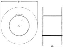


Drum Type (former ref.) Drum Type (new ref.) Width (W1) Diameter without planking* (D1) Weight A 1552 / 1583 15-097-M 948mm 1500mm 92Kg A 1850 / 1883 18-066-M 638mm 1800mm 154Kg A 2150 / 2180 21-114-M 1120mm 2140mm 229Kg A 2157 / 2187 21-115-M 1136mm 2150mm 226Kg A 2159 / 2189 21-195-M 1946mm 2150mm 329Kg A 2550 / 2580 25-141-M 1405mm 2500mm 537Kg A 2551 / 2581 25-143-M 1430mm 2500mm 535Kg Drum Type (former ref.) Drum Type (new ref.) Width (W1) Diameter without planking* (D1) Weight H 2576 / 2586 25-156-S 1560mm 2500mm 541Kg H 3272 32-157-S 1570mm 3150mm 845Kg H 3672 36-165-S 1650mm 3600mm 1362Kg H 3972 39-235-X 2350mm 3900mm 1587Kg H 4272 42-235-S 2350mm 4200mm 1765Kg Drum Type (former ref.) Drum Type (new ref.) Width (W1) Diameter without planking* (D1) Weight L 1192 / 1180 11-077-X 770mm 1120mm 52Kg L 1390 / 1380 13-073-X 722mm 1350mm 76Kg L 1590 / 1580 15-097-X 964mm 1500mm 96Kg 12 Transmission Line Solutions
HELIFLEX SHIPPING & DRUM INFORMATION
RFS offers L, A and H drums to accommodate your shipping and packing requirements.
Radio Frequency Systems (RFS) carefully selects the appropriate reel sizes based on the length and overall diameter of the cable to be wound. A reel not matched to the weight of the cable could be damaged during shipment. Additionally, all cable has a minimum safe bending radius. If it is subjected to bends sharper than the minimum radius, damage to the material is likely. L, A & H drum types enhanced outdoor storage capabilities for typically > 6 months.

HCA78-50 HCA118-50 HCA158-50 HCA300-50 HCA400-50 HCA495-50 HCA550-50 HCA618-50 Former Drum Type Carton 60m Drum type not terminated not terminated not terminated not terminated not terminated not terminated not terminated not terminated L1192/1180 11-077-X 530m L1390/1380 13-073-X 240m A1552/1583 15-097-M 1050m L1590/1580 15-097-X 530m A1850/1883 18-066-M 160m A2150/2180 21-114-M 1050m 630m A2157/2187 21-115-M 120m A2159/2189 21-195-M 750m 230m A2550/2580 25-141-M 250m 120m A2551/2581 25-143-M 900m H2576/2586 25-156-S 1110m 375m H3272 32-157-S 685m 500m H3672 36-165-S 800m 710m 345m 110m H3972 39-235-X 860m 465m 250m 215m H4272 42-235-S 655m 380m 345m 13 Transmission Line Solutions
HELIFLEX ACCESSORY AUTOMATIC DEHYDRATOR
MODEL NAME PRODUCT DESCRIPTION BD552W Dehydrator 208-253VAC, 50/60HZ BD1502W Dehydrator 208-253VAC, 50/60HZ BD4202W Dehydrator 208-253VAC, 50/60HZ BD8402W Dehydrator 208-253VAC, 50/60HZ
INFORMATION ELECTRICAL SPECIFICATIONS BD552W BD1502W BD4202W BD8402W Operating Voltage V 208 - 253 VAC, 50 / 60Hz 220-230 VAC, 50 / 60Hz OperatingCurrent A 3,5 3,9 15 GENERAL SPECIFICATIONS BD552W BD1502W BD4202W BD8402W "max. System Volume @Sea Level" l 5,455 14,863 41,615 83,23 Output Capacity l/h Normal: 413 Continuous; Maximum: 649 Emergency Normal: 1416 Continuous; Maximum: 1770 Emergency Normal: 3068 Continuous; Maximum: 4955 Emergency Normal: 7670 Continuous; Maximum: 9911 Emergency Output Pressure kPa (PSIG) 13.8 - 103.4 (2 - 15) 13.8 - 103.4 (2 - 15) 35 - 138 (5 - 20) 0 - 103.4 (0 - 15) Ouput Air Relative Humidity % >2 RH Number of Outlets 1 Output Fitting Single, 3/8" Press-to-Lock tube fitting Single, 1/2" NPT female Noise Level at 3m dBA 48 63 78,8 Network Management via Web Browser or SNMP through RJ-45 Ethernet Connection
SPECIFICATION BD552W BD1502W BD4202W BD8402W Dimension H x D x W cm 68.6 x 30.8 x 43.8 124.5 x 53.3 x 64.8 124.5 x 53.3 x 64.1 Weight Kg 33,6 36,3 100 120 ENVIRONMENTAL BD552W BD1502W BD4202W BD8402W Ambient Temperature Range °C +5 to +30 Note: Unit will go into SHUTDOWN mode if cabinet temperature exceeds 49°C
14 Transmission Line Solutions
ORDERING
MECHANICAL
PRODUCT SPECIFICATIONS
RELATED PRODUCTS
HELIFLEX ACCESSORY AUTOMATIC DEHYDRATOR


BD552W BD1502W BD4202W BD8402W 6-Month Maintenance Kit P013478 P018302 P012314 P011766 8000 Hour Maintenance Kit P013479 P012252 P011471 P011813 16000 Hour Maintenance Kit P011814 Universal Rack Mnt Kit P011674 P011674 Wall Mounting Kit P011773 P011773 2 x P011773 Installation Kit P011752 P011752 2-Port Manifold w/ Pres Gauges PWM2G 2-Port Manifold w/ Pres Gauges & Valves PWM2GC 4-Port Manifold w/Pressure Gauges PW4MG 4-Port Manifold w/ Pres Gauges & Valves PW4MGC 8-Port Manifold w/ Pres Gauges PWM8G 8-Port Manifold w/ Pres Gauges & Valves PWM8GC Single Pipe Panel P8741SFM Dual Pipe Panel P8741DFM Flow Distribution Panel PFMP2310 Kit, Start up, Dehydrator GLK-1 Kit, Start up, 2 - Port Manifold MLK-2 Kit, Start up, 4 - Port Manifold MLK-4 Kit, Start up, 8 - Port Manifold MLK-8 Gas inlet adaptor 1/8” NPT for 3/8” OD tube TUBE-38OD-PON Gas inlet adaptor M12-G1/8" TUBE-M12-G18 BD552W BD1502W Dehydrator Series BD8402W Dehydrator Series BD4202W Dehydrator Series 15 Transmission Line Solutions
HELIFLEX ACCESSORY ADAPTERS
RFS offers a huge variety of adapters to allow the customers to connect RFS Heliflex cable with existing equipment even the interfaces have different sizes
The high-performance adapters allow maximal flexibility for planning and installation with minimal performance degradation between cable and broadcast equipment

The integration of coupling elements on all adapters with EIA interface allows a design with the shortest space requirement


For installation, where these adapters are not suitable, RFS offers a wide range of 90-degree elbows as a perfect solution where limited space makes a straight cable installation on antennas, switches and combiners impossible.

MODEL NAME INTERFACE 1 INTERFACE 2 DESCRIPTION 78EIA-716M 78EIA 7/16 male Adapter 7/8" EIA to 7-16 Male 78EIA-716F 78EIA 7/16 female Adapter 7/8" EIA to 7-16 Female 78EIA-NF 78EIA N female Adapter 7/8"EIA to N Female 1330M-158EIA 1330 male 158EIA Adapter 13-30 Male to 1 5/8" EIA 1330F-158EIA 1330 female 158EIA Adapter 13-30 Female to 1 5/8" EIA 158EIA-78EIA 158EIA 78EIA Adapter 1 5/8" EIA to 7/8" EIA 158EIAM-78EIAM 158EIA 78EIA Adapter 1 5/8" EIA to 7/8" EIA with Coupling Element 158EIA-716F 158EIA 7/16 female Adapter 1 5/8" EIA to 7-16 Female 158EIA-NF 158EIA N female Adapter 1 5/8" EIA to N Female 318EIA-158EIA 318EIA 158EIA Adapter 3 1/8" EIA to 1 5/8" EIA 318EIAM-158EIAM 318EIA 158EIA Adapter 3 1/8» EIA to 1 5/8» EIA with Coupling Element 318EIA-716F 318EIA 7/16 female Adapter 3 1/8 "EIA to 7-16 Female 318EIA-NF 318EIA N female Adapter 3 1/8 "EIA to N Female 412EIA-318EIA 412EIA 318EIA Adapter 4 1/2" EIA to 3 1/8" EIA 412EIAM-318EIAM 412EIA 318EIA Adapter 4 1/2" EIA to 3 1/8" EIA with Coupling Element 412EIA-716F 412EIA 7/16 female Adapter 4 1/2 "EIA to 7-16 Female 618EIAM-412EIAM 618EIA 412EIA Adapter 6 1/8" EIA to 4 1/2" EIA with Coupling Element 618EIA-318EIA 618EIA 318EIA Adapter 6 1/8" EIA to 3 1/8" EIA 618EIAM-318EIAM 618EIA 318EIA Adapter 6 1/8" EIA to 3 1/8" EIA with Coupling Element 78EIA-R-78EIA 78EIA 78EIA Coaxial line elbow 90° 7/8" EIA 158EIA-R-158EIA 158EIA 158EIA Coaxial line elbow 90° 1 5/8" EIA 318EIA-R-318EIA 318EIA 318EIA Coaxial line elbow 90° 3 1/8" EIA 412EIA-R-412EIA 412EIA 412EIA Coaxial line elbow 90° 4 1/2" EIA 618EIA-R-618EIA 618EIA 618EIA Coaxial line elbow 90° 6 1/8" EIA
INFORMATION 78EIA-716M Coaxial Adapter 7/8’’ EIA - 7-16 male 78EIA-716F Coaxial Adapter 7/8’’ EIA - 7-16 female 412EIA-318EIA Coaxial Adapter 4 1/2’’ EIA to 3 1/8’’ 618EIAM-318EIAM Coaxial Adapter 6 1/8’’ EIA to 3 1/8’’ with Coupling Element 318EIA Elbow 90° Coaxial Adapter 318EIA-R-318EIA
ORDERING
16
Transmission Line Solutions
HELIFLEX ACCESSORY CONNECTORS WITH PERFECT SEALING
RFS offers connectors with O-ring and silicon component Plast 2000 sealing depending on connector size and application. Small connectors with N, 7/16” DIN and some EIA interfaces uses Plast 2000 sealing which has proved itself for decades in the field installation. The easy use and reliability make it the perfect solution for these connectors.


Larger connectors with EIA interface have O-ring sealing which allows an easy reinstallation in case the cable must be adjusted due to equipment replacement, etc. The reuse makes these connectors to the most efficient solution in the field.
NF-HCA78-020

N Female Connector for 7/8’’ Coaxial Cable, RAPID FIT™ Sealing compound
716M-HCA158-001
7/16’’ DIN male connector for 1 5/8’’ Coaxial Cable
618EIA-HCA618-019
618’’ EIA Connector for 6-1/8’’ Coaxial Cable, Gas stop / Gas pass, O-Ring Sealing


ORDERING INFORMATION
NM-HCA78
N Male Connector for 7/8’’ Coaxial Cable, RAPID FIT™ Sealing compound
SEALING METHOD Cable size Interface Model name Plast 2000 O-ring 7/8" N male NM-HCA78-020 x N female NF-HCA78-020 x 7/16" male 716M-HCA78-020 x 7/16" female 716F-HCA78-020 x 7/8" EIA 78EIA-HCA78-019 x 1 5/8" EIA 158EIA-HCA78-020 x 1 1/8" 1 5/8" EIA 158EIA-HCA118-001 x 1 5/8" 7/16" male 716F-HCA158-001 x 7/16" female 716M-HCA158-001 x 7/8" EIA 78EIA-HCA158-001 x 1 5/8" EIA 158EIA-HCA158-019 x 3" 3 1/8" EIA 318EIA-HCA300-019 x 4" 3 1/8" EIA 318EIA-HCA400-019 x 5" 3 1/8" EIA 318EIA-HCA495-001 x 4 1/2" EIA 412IEC-HCA495-019 x 5 1/2" 4 1/2" EIA 412IEC-HCA550-019 x 6 1/8" EIA 618EIA-HCA550-019 x 6 1/8" 6 1/8" EIA 618EIA-HCA618-019 x P2000-001
P2000-002 (70
P2000-003 Cable size Connector cm³ No of tubes cm³ No of tubes No of tubes 7/8" NM-HCA78-020 5 1/4 NF-HCA78-020 5 1/4 716M-HCA78-020 5 1/4 716F-HCA78-020 5 1/4 158EIA-HCA78-020 5 1/4 1 1/8" 158EIA-HCA118-001 10 1/2 1 5/8" 716F-HCA158-001 20 1 716M-HCA158-001 20 1 78EIA-HCA158-001 20 1 5" 318EIA-HCA495-001 120 2 1
(20 CM³)
CM³)
17 Transmission Line Solutions
EIFFEL TOWER

Case Study OVERVIEW
Standing at 330 meters, the Eiffel Tower is one of the most iconic structures in the world. As well as attracting over 7 million visitors per year, the Eiffel Tower houses key connectivity equipment, with its high vantage point making it ideal as a broadcast tower to serve Paris and the surrounding area. However, installing the equipment to make the iconic building act as a powerful transmission site is not without challenges.
18 Transmission Line Solutions
The challenges
Many of our customers have hurdles to overcome when deploying equipment, especially with buildings that have an alternative use. They may need equipment to be concealed to ensure there is no visual impact from the deployment. There may be tight working schedules that limit access for the purposes of installation. They may need our solutions to be tailored to meet the exact needs of their project. When working to upgrade broadcast equipment on the Eiffel Tower, RFS had to find ways to overcome all three challenges.
The solution
In addition to previous projects to provide equipment to bolster the Eiffel Tower’s broadcast capabilities, RFS was selected to deliver the broadcast cabling needed as part of the Digital TV upgrade. For this, RFS provided 450 meters of HELIFLEX 4’’ cable, 810 meters of HELIFLEX 6’’ cable, along with all required terminations and radio electrical measurements.

Rapid deployment
A priority for the project was to ensure minimal disruption to one of the main tourist attractions in Paris. RFS needed to install the 6” cable in a single night to ensure the Eiffel Tower could remain open to tourists.
Discrete installation
The team worked to design and deploy a solution that could be installed with no visual impact on the iconic building.
Tailored requirements
RFS worked with the broadcaster to ensure the cable being deployed would meet both current and future requirements. This would allow the cable to sit in situ, without the need for replacement for the longest possible period of time, minimizing upgrade costs.
Powerful capabilities
The cable installed was used to feed all system antennas situated on one of the highest masts in France, allowing it to serve all inhabitants in the greater Paris area.

The result
RFS oversaw a smooth and successful installation on the Eiffel Tower that continues to meet the demands of the customer. Alongside the Eiffel Tower, RFS broadcast equipment is at work on sites including Bilsdale TV and Radio Tower in the UK, Emitel sites in Poland and for broadcast sites in Kazakhztan; highlighting RFS’s status as the world’s leading provider of broadcasting cable solutions.
19 Transmission Line Solutions
RADIO FREQUENCY SYSTEMS
TO SERVE YOU BETTER Any questions comments or suggestions that would us improve our products and services? Scan this QR code!
WWW.RFSWORLD.COM
01