F EATU RE STORY
aga
The Through-bolt through-bolt Saga The S AN ENGINEERING DETECTIVE STORY BY RIC K FRITH
I
RECENTLY visited Jabiru in Bundaberg to have some 500 hourly service work done on my four cylinder engine. I have now flown over 1,300 hours behind such engines and have followed the through-bolt saga for many years. This saga involves failure of the bolts which hold the cylinders to the engine block and has led to in-flight engine shutdowns, hysterical internet forums and crippling operational restrictions imposed by CASA. Due to my technical interest, and possibly due to my engineering qualifications, Rod Stiff and Sue Woods were generous enough to show me the technical reports on research work which Jabiru has done over many years to solve the problem. In my experience, it is a classic example of engineering detective work.
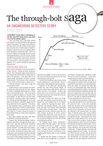
Fig. 1 - Stress Strain Diagram for Steel
STRESS AND STRETCH
When a bolt is stretched, it will initially extend in a linear manner – double the force, double the stretch. This is the elastic region. But as the force is increased, the bolt will reach its yield point and deform like plasticine. It will never return to its original length. Eventually it will reach a tensile limit and break. This is shown in Fig. 1 where the force is ‘stress’ and the stretch is called ‘strain’. If the bolt remains in the elastic range, the bolt should not break. However there is a second property of materials which also affects the life of a bolt - fatigue. If a metal is repeatedly flexed beyond a certain point it will eventually break. How many bends it takes to break will depend on the size of the force applied. At high stresses, very few cycles are required– breaking a paper clip by bending it is a simple example. Breakage can occur even when the material is in the elastic region and not being deformed like the paperclip. Fortunately, for most materials, there is a lower stress, where the piece will survive an infinite number of cycles. These properties are summarised on an SN diagram (See Fig. 2) which shows the number of cycles before failure for a given stress applied to the material. Early Jabiru engines had solid valve lifters and suffered no through-bolt failures. However, when the standard design moved to hydraulic valve lifters, through-bolt failures started to occur. Here was the first clue. Something had changed obviously but what, in particular, was the problem? To further add to the mystery, failures were occurring primarily only in flying school aircraft. At the time of writing, Jabiru data shows every case of through-bolt failure reported to ATSB between 2009 and 2014 was in a flying school aircraft (despite ambiguous phrasing in the March 9, 2016 ATSB report which simply
describes the category of use of the aircraft at the time of bolt failure and ignores the fact they were all flying school aircraft). Furthermore, the failures were mainly in flying schools operating at or near sea level. Those in alpine areas or the tablelands were trouble free. Inspection of the failed 3/8” through-bolts showed they were failing through fatigue, at the point where theory predicted the maximum stress occurred in the threads. However, the stress-strain curve and the SN curve indicated the bolts should have had infinite life at the calculated maximum stress. In order to reduce the failure risk, longer nuts were introduced to ensure the tension was spread over more threads than on the original bolts, significantly reducing the peak stress. While this was partially effective, even longer bolts with even more threads were introduced to further reduce the peak stress. These were installed with Loctite, making it critical the nuts were torqued up quickly to ensure uniform clamping forces before the Loctite set and influenced the force applied to the bolt. Needless to say, this did not always occur in the field, further exacerbating the problem. The strategy behind these modifications was to reduce the peak stress in the bolt and, in accordance with the SN diagram, increase the number of cycles before the component failed. However, even when properly torqued, some through-bolt failures continued to occur, suggesting the problem was not yet completely solved. In parallel with the program to reduce the peak stress in the through-bolts, a comprehen42 / SPORT PILOT
sive research program was undertaken to identify the root cause of the failures. It is this work I studied during my recent visit to Bundaberg. A fundamental breakthrough came when a strain gauge was installed inside a through-bolt to measure the actual stress in an operating engine. When the engine was started, the stress was found to rise unexpectedly high, before declining to the level predicted from analysis. Due to the different thermal expansion properties between the aluminium engine block and the steel bolts, the block expands more than the bolts, increasing the tension in the bolts at operating temperatures. This was expected and is shown in Fig. 3. The surprise finding was that on engine startup, the bolts warmed up much more slowly than the aluminium block, so the block expanded faster than the bolts, further increasing the bolt tension beyond that shown in Fig. 3. As the bolts warmed up and expanded, the tension eventually reduced to the expected level. This observation of thermal stress peak cycling explains why flying school aircraft were experiencing the through-bolt failures. They typically have short flight times (single lessons) and, during each flight, do many touch and goes, imposing higher thermal stresses on each circuit as the engine is throttled back for descent and full power is re-applied for take-off. Furthermore, at sea level, the engine will deliver more power when the throttle is wide open. At higher altitudes, the engine will develop significantly less power. For example at 3,000ft, the loss is almost 10%. At the same rpm, peak cylinder pressure and the stress in the through-bolts are essentially proportional to power, so sea level operations maximise the