
2 minute read
Impactors


■ Aids the flow of dry materials ■ Produces blows of high intensity but low frequency ■ Can be mounted in any position ■ Explosion proof controls are available
Equipment
Advertisement
The Impactor is designed to aid the flow of dry materials that tend to bridge or compact in storage tanks or hoppers. The Impactor produces blows of high intensity but low frequency, and can be adjusted for blow intensity as well as the number of blows per minute. The Impactor and solenoid valve can be mounted in any position. Clean, dry plant air (60 - 120 PSI) is required for operation.
There are several methods to control the operation of the Impactor. Each of them can be wired into an overall system control panel or can be mounted separately in a dust tight control box. Explosion proof controls can also be provided.
The various methods to control the operation are as follows: Manual selection operation - The operator must turn a spring return switch for each single impact desired. On-Off switch operation - The operator turns on the Impactor when the control panel indicates material is not flowing from the bin. An adjustable timer is provided to automatically pulse the control circuit. The operator must turn the control switch off when operation of the Impactor is no longer desired. Parallel to metering valve operation - This control is used when the Impactor is mounted on a bin having a rotary airlock valve on the discharge. Low pressure switch operation - A low pressure switch closes contact when the conveying line pressure is down. Mechanical operation - No electrical controls are provided. A spring return manual control valve is utilized instead of a solenoid valve. The valve must be actuated for each impact desired.
Hopper Cone Section 3/16” x A (rounded corners)
8” Formed Channel x C” Lg.
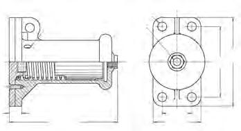
Impactor I-2 Impactor Cross Section

1/2” dia. Vent Port Typ. (4) plcs. (2) 11/16”
Dia. Holes 1/4” FNPT
Air Connection
9-1/2” 7-1/2” I-4 Impactor Cross Section
1/2” dia. Vent Port Typ. (4) plcs. (4) 1” Dia. Holes 1/2” FNPT
Air Connection
9-3/4” 7-3/4”
60-120 PSIG Plant Air 1/2” FNPT Connection Lubricator
3-Way Solenoid Flexible Tubing Air Supply Line D” O.D. x 5ft. Lg. Max.
Electrical Wiring: 120VAC Single
Phase 60Hz 11/16” 8-15/16”

Air consumption (SCFM at 80psig supply)
Impacts/Min. 1-2 1-4 5 < 1 < 2 10 < 2 < 4 15 < 2 < 8 20 < 3 < 12
1-3/8”
11-7/8” 3-1/4” 5-1/4”
Model
Dimensions (inches) Weight A B C D (lbs.) I-2 8x12 4 10 5/16 18 I-4 16x38 8 34 1/2 45


