6 minute read
Tyre Finite Element Analysis – Diversification Of Early Tyre Simulations


The first tyre finite element simulations performed during the 1970s were done to predict deformed shapes and internal stresses and strains, as described in the previous articles of this series. As the 1970s progressed into the early 1980s, additional tyre performance simulations were developed in order to assist tyre development. These developments will be discussed in this and the following article of this series.
Advertisement
Rolling tyre simulations
Some of the first bias tyre simulations reported in the early 1970s, and discussed in the previous articles in this series, predicted results under spinning conditions. One by Zorowski reported tyre shape change and internal stresses due to inflation and free spin. Another by Deak and Atluri included the inertia effects due to free rotation in a road contact solution to predict deformed shape and contact stress. They did not, however, give true rolling tyre predictions.
Simulating the tyre rolling on a road surface requires a full 3D representation of the geometry so that successive nodes around the tyre circumference can come into and leave contact as it rolls. However, the computer resources available at the time limited the tyre models to axisymmetric or very crude 3D representations. Rolling tyre simulations using time domain solution procedures (i.e. explicit dynamics) were many years away.
A novel simulation procedure was developed by Padovan of the University of Akron in the mid-1970s for predicting steady-state rolling tyre results while maintaining the use static tyre modelling methods. Using the Galilean transform, the time derivatives in the governing equations are transformed to spatial derivatives. Inertial effects due to centrifugal and Coriolis accelerations are still included, so no physics are lost in the solution. With the time domain removed, the static solution procedure and modelling aspects can be used.
The first application by Padovan was the prediction of standing waves as a damped resonance phenomenon. His model, reported in a 1977 journal publication, used axisymmetric shell elements to represent the tyre, damping as part of the material properties, and Fourier series to incorporate the circumferential response of the standing wave. His model and a plot from his paper are shown in Figure 1.
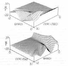
The method was expanded to include road contact of a steady-state rolling tyre, as reported in the 1980 paper by Zeid and Padovan. They used a 2D representation of the tyre for solution efficiencies, modelling the belt/tread and sidewall regions with separate groups of solid elements. A sample of their deformed, undamped tyre results at a standing wave speed is shown in Figure 2.
Excellent AGR Tire Equipment manufacturer
NEW solution of AGR Tire Manufacturing:
High quality of green tire.
2-stage process, integrated flexiable production line.
Fully automatic tire unloading system. Fast & Easy tooling changeover.
IEP (Intelligent equipment platform) based on All-in Building. Supporting IOT (Internet of things) and remote machine commissioning.
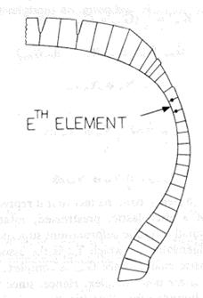
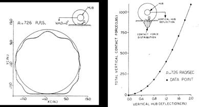
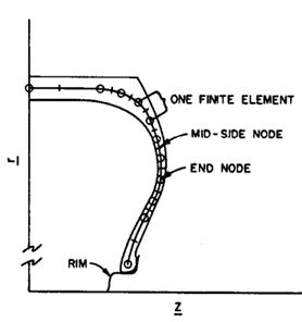
Desiring a 3D representation of the tyre so that design features could be more directly represented, the method was further expanded by Kennedy and Padovan of Firestone and the University of Akron. Laminated shell elements were used for the body of the radial tyre and 3D solid elements were used for the tread portion for better tyre-road interaction. Standing wave speeds of the damped tyre were predicted to show the proper incorporation of the inertia effects in the quasi-static solution. Example results are shown in Figure 3 from our 1987 papers. Faria, Bass, Oden and Becker of the University of Texas showed similar procedure development in their 1989 paper. These formed the basis for the steady-state transport method incorporated into commercial finite element codes in the 1990s.


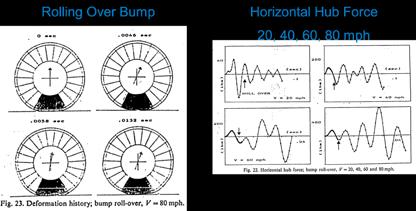
One further expansion of the technique was done by Nakajima and Padovan of Bridgestone and the University of Akron to include transient events in their 2D tyre model. Inertial effects due to steadystate rolling were still incorporated by the Galilean transform technique and a quasi-static solution method, and then the transient dynamic effects were solved in the time domain. Tyre interaction with bumps and holes were predicted; example results are shown in Figure 4 from their 1987 paper.
Natural frequencies and mode shape prediction
The prediction of tyre natural frequencies and mode shapes using the finite element method began in the late 1970s. These early analyses were performed for a tyre under inflation loading only. Half the tyre cross-section was modelled using axisymmetric, laminated shell elements for model size and solution efficiencies. Figure 5 shows results of the prediction of the natural frequencies of a radial tyre from a presentation made at the 1980 tyre finite element symposium sponsored by the ASTM F9 committee by Hunkler, Yang and Soedel of Purdue University and their subsequent published paper. Symmetric boundary conditions were applied at the tyre crown, the tyre was inflated using a nonlinear solution procedure and then the natural frequencies were calculated for this base state. The effect of inclusion or exclusion of the bending-membrane coupling of the cord-ply layers was evaluated and the results compared with measured values, as shown in Figure 5b.
By the early 1980s, the prediction of tyre modes and natural frequencies was becoming a typical part of the finite element capabilities at the tyre companies. Stafford of BF Goodrich showed the first two predicted mode shapes as example output during his presentation on computer-aided design of tyres at the 1983 Akron Rubber Group symposium.
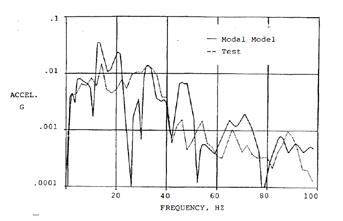
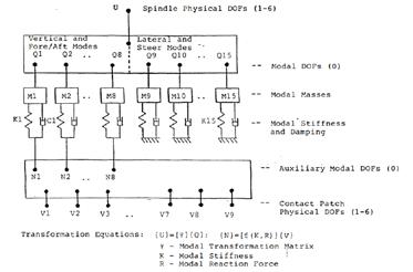
FEA-predicted tyre natural frequency and mode shape results were used in a tyre-vehicle system model to assess ride harshness. A modal FEA model of the tyre, as shown in Figure 6a from a 1987 paper by Kao, et.al. of Ford and Goodyear, used the tyre’s modal dynamic responses to tie the road contact to the hub spindle for a more efficient time or frequency domain solution. The MSC/NASTRAN finite element program was used to couple the modal tyre model with the vehicle model to solve the vibration transmission from the road to the interior of the vehicle. A sample result from their paper is shown in Figure 6b.
Rolling resistance prediction
During the end of the 1970s and early 1980s, finite element simulations to address tyre rolling resistance reduction focused on evaluating reduced material gauges on deformations and strains, as less material in the tyre should result in lower rolling resistance, rather than performing a hysteretic solution to predict energy loss. This could be done via the axisymmetric model simulations discussed in the previous article of this series.
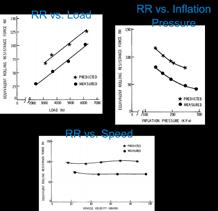
The first true rolling resistance simulation was presented by Whicker, Browne, Segalman and Wickliffe of GM Research at the 1980 ATSM F9 tyre finite element symposium and reported in their 1981 journal article. They developed a multi-module thermo-mechanical simulation procedure that included a deformation module, a dissipation module and a thermal module in order to incorporate the main aspects of the tyre behaviour. The flow chart of their procedure is shown in Figure 7a. A coarse finite element model was used in the deformation and thermal modules, and the effects of speed, load and inflation pressure were predicted. The comparison of their model results and measurements is given in Figure 7b, showing proper trends were predicted by the model.
Air diffusion simulation
Air diffusion has the same mathematical description as thermal conduction, and so could be performed in the available public or commercial finite element programs. In a 1983 report, Coddington of Exxon Chemicals described the use of NASTRAN’s heat conduction capability, with appropriate material coefficients and boundary conditions, to predict a tyre’s inflation pressure loss and the build-up of pressure in the tyre’s crosssection. He used the model as a means of evaluating innerliner permeability and gauge. His model of half the tyre crosssection, shown in Figure 8a, contained 6,000 elements and included the effect of air piping along the carcass cords.
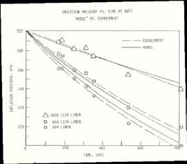
The model compared well with experimental measurements of inflation pressure loss vs time in the assessment of different formulations of innerliner material, as shown in Figure 8b. Prediction of the distribution of internal pressure within the tyre section was also reasonable and is shown in Figure 8c.
Bibliography
Padovan, J, “On Standing Waves in Tires”, Tire Science & Technology, Vol 5, No. 2, May 1977.
Zeid, I. and Padovan, J., “Finite Element Modeling of Rolling Contact”, Computers & Structures, Vol. 4, No. 1-2, 1981.
Padovan, J., “Finite Element Analysis of Steady and Transiently Moving/Rolling Nonlinear Viscoelastic Structure - I. Theory”, Computers & Structures, Vol. 27, No. 2, 1987.
Kennedy, R.H. and Padovan, J., “Finite Element Analysis of Steady and Transiently Moving/Rolling Nonlinear Viscoelastic Structure - II. Shell and Three-Dimensional Simulations”, Computers & Structures, Vol. 27, No. 2, 1987.
Kennedy, R.H. and Padovan, J., “Finite Element Analysis of a Steady State
Rotating Tire Subjected to Point Load or Ground Contact”, Tire Science & Technology, Vol. 15, No. 4, October-December 1987.
Nakajima, Y. and Padovan, J., “Finite Element Analysis of Steady and Transiently Moving/Rolling Nonlinear Viscoelastic Structure - III. Contact / Impact Simulations”, Computers & Structures, Vol. 27, No. 2, 1987.
Faria, L. O., Bass, J. M., Oden, J. T., and Becker, E. B., “A Three-Dimensional Rolling Contact Model for a Reinforced Rubber Tire,” Tire Science and Technology, Vol. 17, No. 3, July-September, 1989.
Hunkler, C.J., Yang, T.Y., Soedel, W.,” A Geometrically Nonlinear Shell Finite Element for Tire Vibration Analysis”, Computers & Structures, Vol. 17, No. 2, 1983.
Stafford, J.R., “Computer Aided Design of Tires”, Akron Rubber Group Winter Technical Symposium, January 27, 1983.
Kao, B. G., Kuo, E. Y., Adelberg, M. L., Sundaram, S. V., Richards, T. R., and Charek, L. T., A New Tire Model for Vehicle NVH Analysis, SAE 870424, 1987.
Whicker, D., Browne, A.L., Segalman, D.J., and Wickliffe, L.E., “A Thermomechanical Approach to Tire Power Loss Modeling”, Tire Science and Technology, Vol. 9, Nos. 1-4, January-December 1981.
Coddington, D.M., “Finite Element Model of Air Diffusion in Radial PC Tire”, Exxon Chemicals Technical Information Bulletin 83ET 380, March 1983 n