16 minute read
Monitoring & Surveillance Improve ESP Operation and Reduce Workover Frequency


Technology Applications
Monitoring & Surveillance Improve ESP Operation and Reduce Workover Frequency
Advertisement
By: M. El Gindy, H. Abdelmotaal, K. Botros, and I. Ginawi, Schlumberger; E. Sayed and T. Edris, Khalda Petroleum Company
Abstract
The Western Desert in Egypt has multiple fields in which most wells are artificially lifted. Wells with ESPs represent the major percentage of oil production by volume in that area. ESP run life is a principal criteria that is typically evaluated before the initial design and throughout the well’s life time. Most wells are remotely positioned from one another and from the main gathering stations (2 to 8 Km. approximately). This is one of the major challenges when trying to maximize uptime and reduce the production deferment. Operational issues including power supply and capacity limitations as well as changing inflow conditions can have negative impact on the ESP run-life, predominantly caused by excessive trips and shutdowns. Also such trips will result in lengthy downtimes due to the remoteness of the wells. On the production side, these trips will ultimately have a major effect on production targets due to intermittent deferment. ESP wells connected to real-time monitoring and surveillance systems incur less lifting costs because of proactive responses and early detection of incidents. Systematic alarms along with pro-active remedial actions can minimize such preventable trips while maintaining the integrity of the ESP, eventually extending its run life. This paper discusses a number of case studies showing how the implementation of such system prevented trips in some situations and allowed making key decisions and recommending remedial actions to optimize the ESP operation.
Introduction
Khalda Petroleum Company is one of the major operators in the Egyptian Western Desert, having a high number of wells (~700 wells) operating within eight different blocks in the area. Nearly half of the total production of the company is from electric submersible pump (ESP) wells. With an objective to continuously increase the production, ESP optimization plays a major role in Khalda’s plans. To aid in the optimization process, a monitoring and surveillance system was implemented on a number of key and high profile wells which were classified according to production rates, water cut and expected recovery.
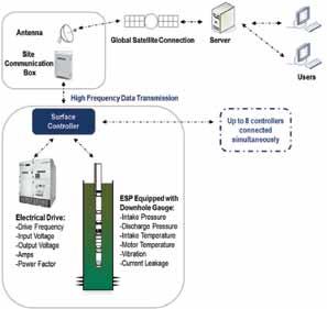
Conventional ESP gauge readings include, intake temperature, motor temperature, intake pressure, discharge pressure and vibration. Essential electrical readings are obtained from the surface equipment, such as motor amps and input voltage. All of these readings are transmitted and displayed at the surface controller as shown in Fig. 1.
The monitoring system in place can be connected to several wells, over several fields. In terms of hardware, a site communication box is connected to the surface controllers of each well (Fig. 1). This unit can practically be connected to up to eight wells at the same time without compromising the data quality.
The data is then transmitted and stored on a server allowing users to view the data remotely via a web based interface. This enables proactive intervention and remedial actions for different scenarios as later discussed in the examples throughout this paper.
Trips versus Alarms
ESP controllers are utilised to set trip points to protect the ESP from undesirable events such as high motor temperature, excessive motor loading or low intake pressure. The ESP stops automatically whenever a single trip point is exceeded.
The monitoring system introduces another level of protection by setting tight thresholds for each parameter and an alarm is sent once the threshold is exceeded. The thresholds are set as close as possible to the average operating value to ensure the slightest deviation is detected. These alarm thresholds act as an additional line of defence to give the operator an additional window to deal with undesired events before approaching the trip point, thus preventing a shutdown.
On the web-based interface, downhole and surface readings can be viewed in real-time. The readings can be updated at regular intervals with a maximum frequency of 1/min. Once an alarm threshold has been exceeded, the system pushes the data to the server and automatically sends alarms to a preset distribution list. The data transmission rate between the well and the site communication box is much higher than that between the box and the server, to ensure such events are captured immediately. In addition to the system induced alarms, dedicated surveillance engineers in an artificial lift surveillance Center (ALSC) analyze the alarms by reviewing the well’s current performance. Based on this analysis more detailed alerts are communicated to the operator indicating the possible root causes leading to the recent events along with the remedial actions and recommendations.
The system also provides certain users the ability to intervene remotely by granting capabilities such as controlling the ESP speed and modifying the trip points, acting as a two way system. This feature proved to be very powerful when dealing with remote locations. Without the remote intervention capabilities, if the ESP is facing a critical event requiring an immediate action, it could take hours in some situations for a field operator to reach the well-site and execute the nessecary actions. The alarms sent by the surveillance engineers are normally classified into three main levels as explained by Camilleri and Macdonald (2010) and highlighted again by AbdelBasset (2012): Ó Concern: level events normally do not pose a direct threat to the ESP, but resolving them will improve the alarming and monitoring Ó Urgent: events pose no immediate threat but an action is required to stabilize the well or improve the performance Ó Critical: events require immediate action The focus of this study is on what we classify as critical events which are those that would normally require an immediate remedial action. Such events, if not addressed; have the potential to greatly compromise the production and ESP overall run life. The following sections highlight some of these events and the means to address them and prevent their reoccurrence.
Case 1: Low Flow Conditions (AG-110 and NQR-2551 wells)
Low flow conditions have multiple negative effects on an ESP operation, particularly with regards to cooling conditions. The motor temperature is highly affected by the cooling provided by the produced fluid passing around the motor housing before entering the pump intake. Operating at a low flowrate for a given motor/casing clearance causes less convection and accordingly a temperature rise. Low flow conditions are also known to trigger other trip points such as the underload setting due to the severe reduction in motor amps. In such situations the most direct remedial action is either increasing the ESP speed or opening up the choke allowing more flow to cool the motor. However, such action also increases the motor load and can consequently increase the temperature. In this example (Fig. 2), the ESP operation became intermittent with frequent high temperature trips. Upon each startup, the temperature would increase gradually with a slight decrease in motor amps. The hypothesis made was a low flowrate and accordingly low fluid velocity which impacts the motor cooling. An initial indication of flowrate changes is the pump differential pressure; so using the real-time data, the differential pressure was calculated and plotted on the same log (Fig. 2). The pump differential pressure starts low and gradually increase until the ESP trips which indicates a gradual decrease in flowrate. This is supported by the gradual decrease in motor current. Production testing measurements of oil, water, and gas rates were obtained on a monthly basis using a test separator. A diagnostics analysis incorporated the downhole measurement along with flowrates which verified the fluid velocity is considerably low. Frequent trips due to high temperature were not only causing undesired intermittent production from this well, but also jeopardizing any chances of achieving the desired run life. An optimisation scenario using the diagnostic analysis was to increase the drive frequency to boost the fluid speed around the motor and improve cooling. After each step, the flowrates, pump differential pressure and motor temperature were observed. The fluid speed effect on motor cooling was dominant in this case as shown in Fig. 2. The motor temperature was reduced by around 15F and the ESP operated smoothly with no more trips. Another example is shown in Fig. 3 where the ESP tripped to due to a high motor temperature. The analysis has shown that the well was experiencing severe depletion leading to a no flow condition. The issue was temporary resolved by shutting the well for some time, in order to allow the pressure to buildup, then the well was successfully started up.
Case 2: Scale Buildup Issues (WRZK-94 well)
Scale that forms during production becomes a potenital problem for pump flowing efficiency and motor integrity. Deposition inside the pump will alter the optimum flowpath and reduce the pumping efficiency, while deposition on the motor housing will form a layer reducing fluid cooling effect.
Intake plugging usually takes place gradually. Such plugging can be noticed when monitoring a number of parameters, including pump intake pressure which would normally increase. If a discharge pressure reading is available, it could specify location of plugging or scale build up, whether it is above or below the pump discharge head.
Three main factors affect the motor temperature at the same time:
Ó Motor temperature increases due to the reduction in cooling, as there is less flow around the motor housing. Ó Motor temperature increases if scale significant scale deposition on the motor housing is present, which reduces the cooling effect created by the well fluid. Ó Motor temperature decreases due to the decreased motor loading, as less flow is being pumped by the ESP. Performing an ESP diagnostic aids in identifying which of the above factors is the dominant case. This diagnostic has to account for the PVT as well as other parameters, in order to accurately simulate the possible optimization scenarios. In the case shown in Fig. 4, it is evident that the intake pressure started to increase along with the motor temperature and at the same time, the average amps started to decrease. The issue was identified, as partial intake plugging and an acid backwash job was performed accordingly. The plugging was cleared and the intake pressure dropped back as expected. However the motor temperature started to increase again as observed in Fig. 4 which is most probably due to scale deposition on the motor housing itself, subjecting it to poor cooling conditions. This issue was temporarily resolved by reducing the motor speed, effectively reducing the load and the motor temperature as modelled in the diagnostic analysis. However the temperature continued to increase overtime and a more permanent solution was required. The issue was then resolved by performing another acid back wash job, while subjecting the ESP to a longer soak time. The success of the second acid back wash attempt is demonstrated in Fig. 5. The motor temperature decreased by 50 degrees F (From F 285 to 235 F), as the longer soak time dissolved the scale on the motor housing, leading to improved cooling conditions.
Case 3: Dead Head (MRZK-78 well)
A Dead Head condition occurs when there is an obstruction above the ESP, restricting the fluid path to the production facilities. Having a dead head can be one of the most critical situations facing an ESP. This dead head will normally cause the ESP to rapidly heat up in a short period of time until it eventually reaches its trip point. Having excessive events like this, will subject the motor to cyclic drops and rises in the motor temperature. This behavior can greatly reduce the ESP’s run life and lead to a pre-mature failure. Fig. 6 shows an example of an ESP facing a Dead Head event. This is clear in the sudden rise of the motor temperature and the drop in motor amps, since no more fluid is being produced to the surface. A trip was prevented by the surveillance engineer and the field personnel were notified accordingly. The cause was identified as malfunctioning of the adjustable choke causing it to close, resulting in a complete restriction of the flow.
Case 4: Pump Off (SIWA 2-L2 well)
In a pump off case, an ESP basically ceases to pump any liquids due to the excessive drawdown created by the ESP. This normally happens when the liquid column inside the wellbore drops below the intake level. At this stage, gas maystart to occupy the ESP stages and liquid no longer reaches the surface.
These events can be common when dealing with reservoir depletion or loss of pressure support, which can be quiet common in mature fields. Such events can be prevented by closely monitoring the intake pressure. In the example shown in Fig. 7, it is clear that the intake pressure was showing a decreasing trend. The surveillance engineer observed the ESP performance and accordingly notified the field personnel. A potential trip was avoided by controlling the drawdown by reducing the ESP frequency, leading to a stable ESP operation.
Case 5: Recirculation (MRZK-52 well)
Detecting recirculation can be challenging, because of the several possibilities involved. In the example shown in Fig. 8. The ESP was installed with a reused ESP bypass system (Y-tool). By-pass systems introduce an extra level of flexibility to the completion since it enables well interventions (Wireline, coiled tubing, slick line. . .etc.), without pulling the ESP out of hole. A blanking plug is installed in the bypass section to prevent flow re-circulation during the normal operating conditions. In this case, the surveillance engineer reported a low differential pressure after starting up the ESP, even though the well was still producing. This low differential pressure acts as one of the recirculation symptoms. This was correlated with other symptoms, including the intake temperature rise and low motor amps. The blanking plug’s integritywas doubted and all symptoms were supporting the circulation hypothesis (Fig. 9). The
plug was pulled by wireline, redressed, and then rerun. After restarting the ESP, the surveillance engineer again reported a low differential pressure. A workover rig was already at the wellsite to pull the completion out of hole but a last attempt was agreed with the ESP operating team to change the wireline plug one more time.
The final attempt was successful and the production was restored to the expected range. Trusting the monitoring and analysis saved a workover cost and pre-mature ESP failure. This ESP has been running for 5 years and still running as of September 2015.
Results
The implementation of a monitoring & surveillance system has shown a proven positive impact on ESP run life. Fig. 10 shows an increasing trend in average run life ever since real-time monitoring and surveillance have been introduced in the Khalda.
Two main performance factors can be used to evaluate the ESP run life:
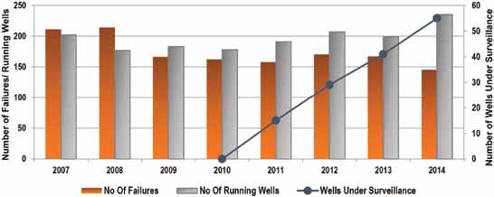
Ó Average number of ESP failures over a given field. Fig. 11 shows the average number of failures experienced in
Khalda wells. We can observe a drop in the number of failures, even though the number of ESP operated wells is on the rise.
Ó Average ESP Run life, which in this case it is based on the mean time between failures (MTBF) moving equation as explained by J. Hogan (2000):
For this study the MTBF calculation also assumes that all of the running wells before the current year are considered to be starting at the beginning of the year (moving method). So if a well has been running for 8 years, it is assumed to be only running from the start of the current year. Fig. 10 shows what appears to be an increasing trend in MTBF, since the surveillance system has been introduced, indicating the impact of the surveillance service. Having an increasing trend with such conservative calculation shows the value of real-time Surveillance and close collaboration between the surveillance engineers and the field operators.
Conclusion
1.ESP real-time surveillance is becoming more essential and is considered a necessary tool when it comes to production optimization. The availability of such technology also increases the level of collaboration among the field operators, office personnel and the service providers. 2.As with any mechanical system, excessive shut-downs and trips can greatly reduce the run-life of the ESP. Realtime surveillance can minimize such trips and eventually prolong the run-life of the entire field. 3.Having tight alarm thresholds ensure that any critical event is detected, giving the operator a head start to investigate and prevent undesirable operations. 4.Data gathering and monitoring can present a serious challenge when dealing with multiple wells scattered over several kilometers. Having a monitoring system along with dedicated surveillance engineers, gives the operator the ability to perform remedial actions in a timely manner.
Such actions reduce the amount of deferred oil and can even directly save workovers, which would have not been prevented otherwise.
REFERENCES
1. Abdel-Basset, M., ElBarkatawy, A., M. Elsherif, M. et al. 2012 How Real-Time Surveillance 2. Improves the ESP Run Life, Uptime and Reduces Production Deferment. Presented at the SPE Oil 3. and Gas India Conference, Mumbai, India, 28–30 March. SPE-155336-MS. 4. Camilleri, L., and J. Macdonald, J.; 2010, How 24/7 Real-Time Surveillance Increases ESP Run Life 5. and Uptime. SPE Paper presented at the SPE Annual Technical Conference and Exhibition, held 6. in Florence Italy, 19–22 September. SPE-134702-MS. 7. Hogan, James R. 2000, Is There A Shift in the ESP Run Life Paradigm. Presented at the 2000 8. Electrical Submersible Pump Workshop, Houston, Texas, 26–28 April.
Figure 1—Schematic explaining the monitoring & surveillance system components and hardware
Figure 2—Low flow conditions (case 1) causing the ESP to trip several times due to the low loading. The issue was resolved by increasing the speed, hence the drawdown.
Figure 3—Low flow conditions, due to severe depletion. The well tripped and was shutdown for some time to allow the well to buildup enough pressure.
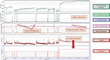
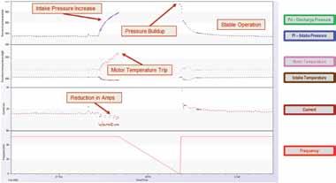
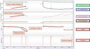
Figure 4—Partial plugging due to scale deposition (case 2). The issue was identified and the scale an acid back was job was performed. However the motor temperature continued to rise and the ESP speed was reduced to temporary reduce the temperature.
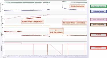
Figure 5—Same ESP as in Fig. 3. Scale was still deposited on the motor housing affecting its cooling. A second back wash job was performed was with a longer soaking time to remove any remaining scale on the motor housing. As a result the motor temperature was reduced, due to the improved cooling conditions.
Figure 6—Dead head conditions (case 3) due to a choke malfunction
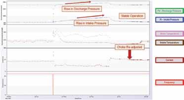
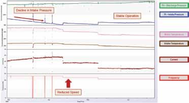
Figure 7—Pump off conditions (case 4) and the means to mitigate it. In this case once a decline in intake pressure was observed the speed was reduced accordingly.
Figure 8—Recirculation (case 5) as observed by the minor differential pressure. After replacing the Y-tool plug a differential pressure was observed indicating that the ESP is producing all of the fluid to the surface.
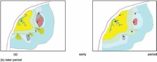
Figure 9—Schematic illustrating the recirculation phenomena when dealing with a leaking Y-tool plug.
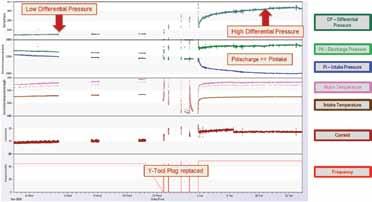
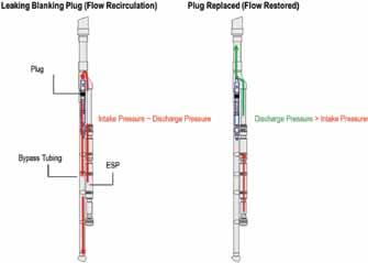
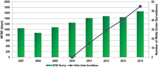
Figure 10—Rise of average ESP run-life in Khalda and the number of wells under surveillance
Figure 11—Number of ESP failures versus number of running wells throughout the fields operated by Khalda