
12 minute read
Very Long Step-out Subsea Umbilical FastTrack Design Approach based on


Technology Applications
Very Long Step-out Subsea Umbilical FastTrack Design Approach based on Zohr Experience
Advertisement
By: Sameh Elsabbagh, Enppi; Hesham Elkhafif, Petrobel
Abstract
Design of deepwater Subsea Control & Umbilical Systems is a challenging process subject. Challenges are emerging from subsea flow assurance ever demanding requirements as well as control and data transmission implications through long step-out. Zohr project Accelerated Start-up Phase FEED design adopted a Centre Control Platform (CCP) to accommodate the chemical injection, power & control Topsides facilities feeding and controlling subsea equipment at different drill centres through umbilical network. Subsea control is based on enabling multiplexed electrohydraulic Subsea Production Control System (SPCS) with Fiber Optic (FO) communication. Control of each drill centre is independent based on segregated power and data transmission scheme. The development adopted tight schedule due to the significance to country economics. Chemical Injection and control with related data transmission through very long step-out umbilical has demonstrated to be a complex job in terms of assuring reliable connection of the CCP with subsea equipment located about 160km far away from the CCP. This complexity is merited to tight coupling between SPCS, umbilical system and installation engineering. Also, the heavy impact of failure downtime attributed to production loss along with increasing cost of intervention has significant footprint on every design aspect. The current paper highlights a Fast-Track parallel design approach for very long step-out subsea development based on Zohr project achievements. With the tight schedule and massive amount of material involved in umbilical manufacturing (i.e. 2.2millions meter cables, 2million meter of tubes, and 2.7 million meter of fillers), any change after umbilical purchase order issuance will have significant impact on project execution and will probably put the project schedule into major risk. The traditional relay-based design scheme is replaced with an approach minimising the dependency of Umbilical Design on SPCS and Installation engineering. The criticalities include impact of power distribution/ sparing scheme on electrical cables configuration and design of Umbilical Termination Assembly. Also, the work covers FO link budget design challenges, need for midway repeater and related impact on connection design between main umbilical sections. The proposed approach is supported with conservative deployment scheme to eliminate installation risks. Finally, the paper will conclude with a summary for key aspects to be taken into consideration during FEED in case of very-long step-out projects. Very-long step-out subsea field development projects being limited worldwide, the work will be valuable reference for similar future projects as being handling technicality from project management perspective.
INTRODUCTION
Very long step-out umbilical design is challenging due to the need for edge design parameters making it unique. Also, the schedule requirements for Zohr project added an extra perspective for the challenge by adopting an overall 14 months for the umbilical from placement of Purchase Order
(PO) up to Load-Out LO from manufacturer quayside. In the early start of the project, the challenges associated with the Main Umbilical very long step-out and the corresponding extended design cycle requirements were planned to be avoided by an initial Plan of Development (POD) calling for temporary locating the control equipment / chemical injection skids on a rental intervention vessel or FSPO in case the onshore facility and the first 26inch pipeline anticipation could not be achieved. With the adopted key design points that will be discussed and thanks to Umbilical contractor capabilities, the complete schedule for Umbilical system design and manufacturing of required umbilical lengths for Main Umbilical trunks and the infield umbilicals awarded was 14 months delivery date. Zohr deepwater field development has been optimized as per the following points: Ó Existing platform has been deleted as the schedule for the new CCP had been improved in order not to be in the critical path for the project. New CCP hosts Topsides control and chemical injection equipment needed for Zohr full field.
Ó Gas production lines have been optimized by increasing the RUP/plateau extension phase gas production pipelines
OD from 26» to 30» which led to reduce the total required number from 6 × 26» to 1× 26» plus 2 × 30» Ó Service line size modified from 8» to 14»
Ó 4 off additional wells relevant to RUP North culmination have been considered to be controlled by the same main umbilical trunk serving the first 6 off wells foreseen within accelerated production phase.
DESCRIPTION OF UMBILICAL DISTRIBUTION NETWORK
In the current development scenario, the laid Main umbilical, of 158km length, was split into two almost equal sections through an In-Line-Connector (ILC) to allow flexibility for selection of Installation vessel.
The Main umbilical serving ASU development (6 wells), Optimized RUP North (+4 wells) and relevant Subsea Control System, has the capability to supply power and communication to a total number of 24 SCMs with the following architecture:
UMBILICAL PARALLEL DESIGN APPROACH BASED ON DECOUPLING OF IMPACT ON INTERFACE REQUIREMENTS WITH PROJECT PACKAGES
Due to the significance of production start date for the country economics, a very tight schedule was adopted through all project phases starting from FEED, detailed engineering, fabrication and installation. The design of Umbilical was put in parallel with Project packages in order to eliminate extended time associated with the relayed design approach. An extreme care was expended to decouple effect of interface parameters between different packages by adopting worst case values / scenarios for interface parameters. Each emerging interface was extremely scrutinized to figureout the impact on involved packages and to identify the parameters in each package that could be improved without schedule impact. The next paragraphs will discuss some of the interfaces encountered along with solution adopted as an improvement for long step-out umbilical smooth Fast-Track Design.
CABLE CONFIGURATION FOR LONG STEP-OUT UMBILICAL
This interface between SPS and Umbilical is extremely affecting Umbilical cross section design. Umbilical manufacturing schedule could be impacted by the selected Cable configuration where the cable configuration controls the number of paths to achieve Umbilical layup. The shortest schedule for umbilical manufacturing is achieved with single path lay-up. As a rule of thumb, the number of elements to be laid-up in the umbilical shall not exceed the number of element reels that can be accommodated on planetary machine in order to be able to achieve a single path lay-up. Though Cable configuration is strongly linked to the SPS architecture and the related Electrical/ Optical Distribution Network sparing / segregation philosophy, Cable configurations based on Electrical Quads and Multi-bundle FO cables can be adopted in an early design phase to cater for all channels / Drill centers connectivity requirements without increasing the number of elements in the Main Umbilical. Channels from different drill centers can be grouped together in the same cable in order to maintain the segregation philosophy. Tuning with the final SPS architecture can be achieved through proper FACT design which allow to the splitting of the Electrical QUADS and FO bundles into the number of needed subsea connectors.
FIBER OPTIC CABLE GRADE / ATTENUATION PARAMETER FOR LONG STEP-OUT UMBILICAL
This interface between SPS and Umbilical showed major importance and from first day there shall be a very clear Optical Power link budget. SPS Contractor adopted a design with 160km length between the Master Control
Station (MCS) and the first subsea modem based on an attenuation figure achieved in a previous project with FO cable attenuation of 0.185dB/Km. Contractual parameter of the awarded umbilical FO cable attenuation was 0.22dB/ Km. The conflict appeared during the progress of the FO communication analysis while the Umbilical contractor achieved a big progress in manufacturing of FO cables (i.e Cable Drums for a total length of 44km had been manufactured out of the 160km before the conflict appeared). It was investigated to adopt midway repeater solution. However, the ILC was in a very late stage and implementation of design modification to allow for retrievable mid-way repeater showed to have severe impact on Umbilical schedule due to optical connectors long lead time. Also the umbilical needed to be retrieved while in operation to get the modified structure supporting for retrievable repeater installed on the ILC later on which proved to be very complicated task. On a second parallel track, a conversion of UTAs design to be adopted midway was raised to allow for a future midway repeater to be connected upon need; however, this proved to delay the midway terminations and consequently the scheduled Load-Out (LO) date. On a third track, manufactured cable parameter was scrutinized and showed to be within the needed limit. FO link was extremely analyzed to secure the FO optical power budget. Manufacturing splicing and connector points that might lead to degradation of the overall cable attenuation parameter were identified and points of splicing / connection with potential optical loss were identified and further controlled. Though the FO cable attenuation parameter controlled during the ASU phase, having a step-out of about 160km is a major project risk and the best approach to adopt midway repeater – even if confirmed not needed by SPS contractor.
MIDWAY ILC VERSUS MIDWAY UTAS
The Main Umbilical length in ASU phase was about 160km. It was decided to adopt midway non-retrievable In-lineConnector (ILC) in order to divide the 160km into two nearly equal sections as a flexibility for the selection of installation vessel. The Main-umbilical being the vital link between the SPCS and chemical injection topside equipment at central control platform and the deepwater field, ILC was designed to eliminate any source of failure due to the introduced electrical and hydraulic connections. Although the ILC proved to be very reliable, it showed to be a limiting factor during the detailed engineering as it had not allowed for integration of midway repeater as described in next paragraph. Also, the ILC makeup to connect both sections of main-umbilical trunk demonstrated to be offshore critical operation as well as necessitating a standby time of more than 1 day for performing the rigging/ alignment / connections of EL & FO connectors. This required to change the design of one ILC end had been modified to allow for subsea abandonment, wet storage and later retrievability in case the weather conditions are not suitable for an extended period of umbilical hang-off. A lot of care was performed during the scheduling of the offshore campaign to position the Main umbilical laying in a slot allowing for secured the weather window during main umbilical installation campaign.
BOLTED UTA VERSUS RETRIEVABLE UTA AND UMBILICAL SUBSEA TERMINATION INTERFACE CAPACITY
The interface between the UTA and the Umbilical Subsea Termination Interface (STI) proved not only to be dependent only on SPS and UMS contractors but also critically depending on the Installation scheme as it was affected by the type of UTA – UTA Foundation Base Interface (i.e. whether UTA frame is bolted to mudmat or is retrievable). Although the UTA Flange interface was highly rated to cater for about 800kN Tension/ Umbilical Installation load and about 300kNm Bending moment which cater for installation for UTA with Mudmat, the STI interface and the Bend restrictors were limited to 100kNm bending moment which was found to be non-satisfactory for both 1st & 2nd end UTA installation. 1st end UTA deployment limitation was due to that center of Gravity of the UTA with Mudmat is misaligned with the lifting points causing a high bending moment tending to rotate the UTA during the Transfer / uprigthing from vertical to horizontal position. 2nd end UTA was due to the weight of the BR elements itself. The breaching of STI & BR elements capacity was due to that the installation analysis was done with a very conservative assumption of no usage of installation aids. 1st end UTA installation bending moment could be reduced by attaching a big clump weight to the front padeye and uprighting by adjusting the vessel offset in a better controlled manner. This would highly reduce the applied moment during both upending and landing. 2nd end UTA installation bending moment could be reduced by applying buoyancy module to carry out the weight of the BR elements and limit the Bending moment. The usage of installation aids was decided to be kept as a contingency during offshore to assure extreme integrity of equipment while deploying. Many installation cases were considered and complete graphs of the Bending moment were developed to get control on the variation of the Bending moment at different steps along the Umbilical starting from the UTA interface flange. After the interface being thoroughly investigated, the mitigation adopted to solve criticality of this interface at a late stage was to upgrade the STI and BR elements capacity. Capacity of STI was upgraded by either changing the bolts
or adopting welding at critical points as applicable. BR elements thickness was increased to cater for 240kNm bending moment instead of 100kNm. The lead time needed for both STI and BR elements did not impact termination activities and the overall schedule was successfully preserved. Although bolted UTA-Mudmat system was reducing the number of installation activities, the bolting of the UTA frame to Mudmat proved to be complicated operation consuming a lot of offshore time and necessitating an extended weather window to avoid umbilical fatigue in sagebend. As a conclusion retrievable UTA designs were adopted for next phases for the purpose of decoupling the UTA-Mudmat system design from Umbilical and Installation details. With the same target, independent from whether the UTA – UTAFB interface is bolted or retrievable UTA, a string of BR elements with different bending moment requirements shall be adopted allow for high bending moment capacity at the interface with UTA as a rule of thumb.
CONCLUSION AND RECOMMENDATIONS
As highlighted above, during the course of Zohr project there were solved challenges and achieved design improvements. This gained experience is worth to be considered in future projects for very long step-out Umbilical system FEED. Accordingly, a summary of interrelated design parameters is provided showing the scope of impact on other parameter. Following this list, Design capacity, interfaces decoupling and flexibility during project execution could be verified with overall schedule reduction.
Figure 1—Updated development Scheme
Figure 2—Subsea Control System ASU + ORU development


Figure 3—Umbilical Lay-up process

Figure 5—ILC needed modification for retrievable Midway repeater
Figure 4—Cable configuration used in Zohr RUP phase allowing decrease of number of elements in the Main umbilical
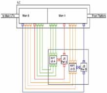
Figure 6—ILC midway repeater connectivity

Figure 7—Midway repeater by changing over to Midway UTAs
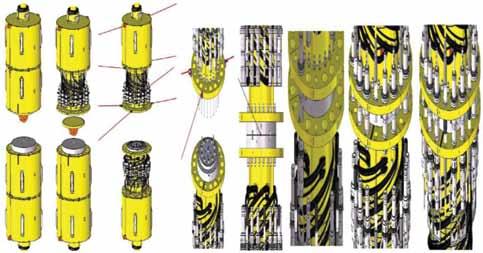
Figure 8—Steps of ILC ends connection offshore.
Figure 9—1st end UTA deployment with STI/BR elements subject to high moment due to misalignment of Center of gravity of Bolted UTA-Mudmat system with Rigging during Transfer/ Uprighting operation

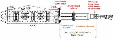
Table 1—Comparison between Capcity requirements for UTA bolted and Retrievable UTA designs

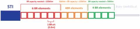
Figure 10—Scheme of the needed Capacity for BR elements.


